Mastering LRF Electrical Noise Suppression and EMI in Drone Gimbal Integration
Bolting an eye-safe 1535nm laser rangefinder into a multi-axis gyro-stabilized drone gimbal seems straightforward until the brushless motors wake up. The moment your pan-tilt actuators track a moving target, your telemetry stream begins reporting nonsensical data: impossible returns at forty meters, jittery distance drift, or complete dropouts on distant vehicles.
The laser optics didn't degrade, and atmospheric fog didn't roll in. You are dealing with severe electrical cross-talk packed inside a fist-sized aluminum shell. Achieving effective LRF electrical noise suppression requires recognizing that a nanosecond optical receiver shares physical space with high-current motor drivers. Uncontrolled EMI in drone gimbal integration will quickly turn an advanced aerial payload into an unreliable sensor suite.
The Harsh Electrical Environment Inside a Multi-Axis Gimbal
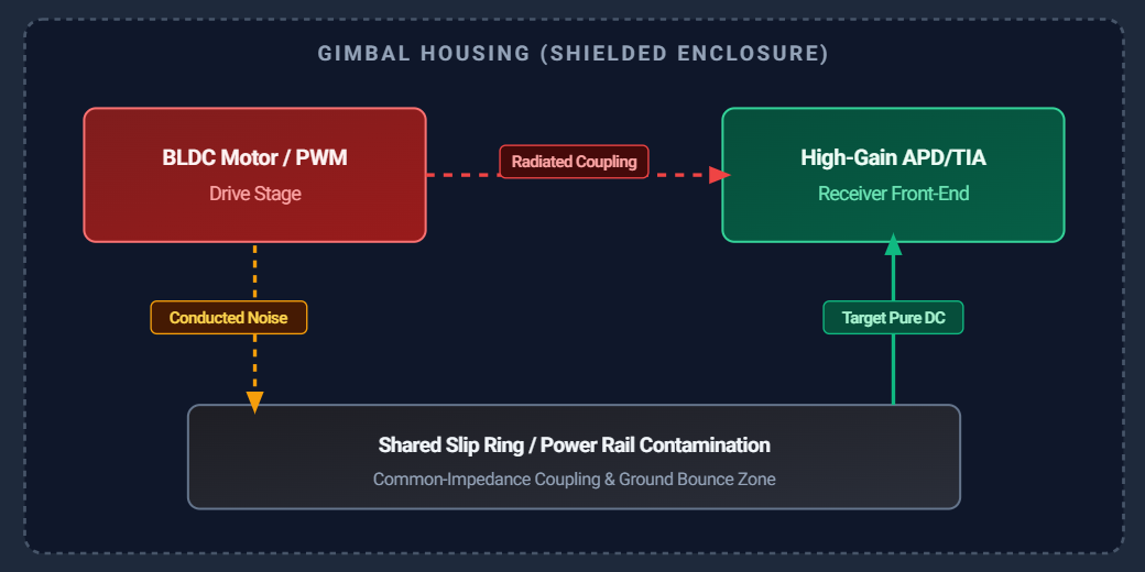
Miniature drone pods force conflicting physical domains into tight proximity. Structural weight cuts demand thin metal skins or carbon composite shells. As a result, sensitive optical detectors sit just millimeters away from high-torque brushless DC (BLDC) motors, shared slip rings, and switching step-down converters.
Brushless Motor PWM Drives and High-Frequency Radiated Fields
Gimbal motors rely on pulse-width modulation (PWM) driven by field-oriented controllers switching between 20 kHz and 50 kHz. Every cycle creates steep current steps (di/dt) and rapid voltage transitions (dv/dt). These fast switching edges radiate broadband electromagnetic spikes straight into adjacent bays.
Stator Switching Spikes vs. Analog Optical Front Ends
Unshielded motor coils act as small broadcast antennas. When magnetic fields collapse during commutation, they induce small currents across nearby copper traces. Because your rangefinder preamplifier sits right beside the pan or tilt stator, it picks up these bursts directly. If unaddressed, the analog comparator interprets a motor commutation pulse as a light pulse returned from an object downrange.
Slip Ring Trace Contamination and Conductive Bleed
Mechanical joints present a severe challenge. Hollow-shaft slip rings and flexible flat cables run motor power, video feeds, and serial commands side by side. Running unconditioned DC power parallel to high-gain sensor lines invites capacitive coupling. Noise bleeds across conductors over mere centimeters of shared routing, sneaking right past external shielding.
Power Supply Ripple Effect on LRF Receiver Sensitivity and Accuracy
Pulsed time-of-flight units emit short optical pulses—often 3 to 6 nanoseconds wide—with peak power in the kilowatt range. By the time that beam strikes an uncooperative target ten kilometers away and scatters back, the returned signal is down to picowatts. Capturing that faint optical pulse demands immense amplification. Under these operating conditions, the power supply ripple effect on LRF receiver stages can degrade system performance immediately.
High-Voltage APD Bias and Transimpedance Amplifier Demands
Long-distance rangefinders use an InGaAs Avalanche Photodiode (APD) reverse-biased near its breakdown threshold, paired with a multi-gigahertz transimpedance amplifier (TIA). This circuit converts microampere photocurrents into crisp logic transitions within nanoseconds. Any noise riding on the APD high-voltage line or the TIA's DC rail gets boosted right along with the optical return.
Sub-Millivolt Rail Fluctuations vs. False Threshold Crossing
When supply ripple reaches the receiver board, the baseline noise floor rises. If the detection comparator threshold sits too close to this noisy baseline, ripple peaks trip the comparator directly. The rangefinder treats this as a target strike, outputting ghost readings at close range.
If firmware simply raises the comparator threshold to hide the noise, small signals get dropped entirely. A system capable of 10-kilometer ranges drops down to 3 or 4 kilometers because weak signals are swallowed by the raised threshold.
Time-to-Digital Converter Jitter and Distance Drift
Time-of-flight physics is direct: every 6.67 nanoseconds of clock jitter introduces one meter of ranging error. When voltage instability affects the time-to-digital converter (TDC) or discriminator logic, trigger points wander along the pulse slope. Instead of steady returns within a 0.5-meter window, distance values bounce wildly between successive shots.
Stopping Laser Rangefinder False Triggering Motor Noise at the Source
Eliminating laser rangefinder false triggering motor noise requires cleaning the electrical paths before noise enters the optical housing. Software post-filtering alone will not restore lost optical receiver sensitivity.
Cascaded Power Filtering for High Repetition Rate Pulses
Firing a solid-state or diode laser at 1 Hz to 20 Hz draws abrupt current surges during pump discharge. Meanwhile, the receiver front end demands ripple-free power. A single switching regulator cannot feed both stages directly.
Implement a multi-tier power topology:
Place a common-mode choke right where the cable enters the pod.
Route power into a pi-filter ($C-L-C$) to strip high-frequency switching residue.
Drop the voltage down using ultra-low-noise linear low-dropout regulators (LDOs) with high power supply rejection ratios (PSRR) dedicated strictly to analog signal paths.
Passive Component Selection: Ferrites, Polymers, and TVS Clamps
Choose components tailored to your drive electronics:
Ferrite Beads: Select parts with peak impedance between 10 MHz and 100 MHz to suppress the sharp ringing edges of motor drive switches.
Transient Voltage Suppressors (TVS): Mount low-capacitance TVS diodes directly at the supply inputs to clamp inductive flyback when motors decelerate suddenly.
Filter Capacitors: Combine low-ESR solid polymer capacitors for bulk charge storage with small 0.1 µF and 100 pF ceramic capacitors mounted adjacent to IC power pins to shunt radio-frequency spikes directly to ground.
Isolated Star Grounding Topologies
A ground trace has measurable impedance. When rapid return currents from motor coils cut across the rangefinder's analog ground, small voltage drops appear between reference points. Isolate power grounds, digital logic grounds, and sensitive analog return paths on separate PCB layers, bonding them at a single mechanical star point on the chassis. This arrangement keeps motor return currents away from analog reference planes.
Shielding RS422 Cable for Drone Gimbal Slip Rings and Cavities
Long-distance rangefinders use RS422 differential links to push target ranges, elevations, and diagnostics to flight controllers. While differential pairs reject external field noise through subtraction, poor wiring practices can destroy that common-mode balance. Careful shielding RS422 cable for drone gimbal runs preserves serial data across tight internal cavities.
Common-Mode Rejection Balance Across Moving Hinges
RS422 depends on equal and opposite voltages traveling along twisted conductors. When an external electromagnetic field cuts across the harness, both lines pick up equal noise voltages, allowing the differential receiver to subtract the interference.
If lines pass through a slip ring where twists untangle or trace lengths vary, that symmetry breaks down. Noise couples unevenly into the lines, generating differential errors that corrupt telemetry frames and drop serial packets.
360-Degree Backshell Bonding vs. Inductive Pigtails
The most frequent wiring mistake in payload assembly is stripping the braided shield, twisting it into a two-inch wire lead, and soldering it to a pin. This "pigtail" introduces parasitic inductance that blocks high-frequency currents, transforming the shield into an unintentional radiator inside the shell.
Always terminate cable shields using a 360-degree conductive backshell clamp bonded straight to the metal connector body or housing wall. This preserves an unbroken RF shield around the conductors.
In-Line Ferrite Sleeves for Data Lines
Space limits inside gimbals often force serial lines into the same conduits as DC motor power. Clamping high-permeability split ferrite beads over twisted RS422 pairs at the slip-ring exit strips common-mode noise while preserving high-baud serial edges.
Systemic EMC Design for Optoelectronic Payload Assemblies
Addressing components individually only solves part of the challenge. A dependable EMC design for optoelectronic payload systems treats the enclosure, optical glass, internal boards, and structural mechanics as a single, unified shield.
Chassis Grounding Across Composite and Aluminum Frames
Carbon-fiber arms and brackets provide high strength with minimal weight, but poor electrical conductivity can create uneven potentials across chassis joints.
Use chromated or nickel-plated mating surfaces on all internal aluminum mounting blocks.
Avoid relying on anodized layers for ground paths; anodizing acts as an insulator.
Mount the rangefinder body directly against the structural gimbal yoke using conductive hardware to create an equipotential Faraday shield that blocks radiated motor fields.
Optical Aperture Windows and Conductive ITO Coatings
Metal chassis walls block electromagnetic fields, but optical beams require an open window. This aperture provides a path for radiated interference to enter or escape. In high-power RF or motor-dense environments, opt for front windows coated with a transparent conductive layer, such as Indium Tin Oxide (ITO) tuned to transmit 1535nm light. Grounding the conductive window edge directly to the enclosure frame extends the Faraday cage across the optical port without disrupting laser transmission.
Huanxin Measurement & Control Technology Custom Solutions
Off-the-shelf optical sensors rarely drop cleanly into compact stabilized turrets. Huanxin Measurement & Control Technology Co., Ltd. develops specialized 1535nm pulsed laser rangefinder modules (covering 3 km, 5 km, 8 km, and beyond 12 km) engineered for tight aerial pods.
Our modules incorporate multi-stage power supply filtration, internal shielding, isolated ground domains, and ruggedized RS422 interfaces. We routinely customize housing geometry, supply input ranges, and connector configurations to meet payload volume constraints and suppress electrical noise before field operations begin.
Diagnostic Bench Testing and Field Validation
Never clear a gimbal payload for flight operations based solely on static bench tests with stationary motors. Dynamic validation is essential for catching intermittent electrical issues.
Near-Field Sniffer Probing and High-Bandwidth Scopes
Troubleshooting noise in a packed assembly requires dedicated bench tools:
Near-Field Probes: Sweep miniature magnetic field (H-field) sniffer probes across motor driver FETs, slip-ring harnesses, and enclosure seams to detect localized RF leakage.
Spring-Ground Scope Probes: Standard alligator clips add ground-lead inductance that hides fast spikes. Inspect DC power rails and APD bias monitor points using high-bandwidth oscilloscope probes fitted with short spring ground tips.
Dynamic Stress Profiles: Drive the gimbal through high-speed pan, tilt, and stabilization routines while firing the laser at maximum rep rates against a calibrated target board. Watch for range dropouts, measurement standard deviation increases, or dropped telemetry packets under peak motor loads.
Engineering Reliable Aerial Ranging
Getting clean range measurements out of a high-agility drone gimbal requires balancing optical performance with disciplined electrical shielding. By filtering motor switching spikes at the source, smoothing supply rails to protect APD bias networks, terminating harness shields with 360-degree bonds, and maintaining chassis ground continuity, you eliminate false triggers and preserve detection range.
Partnering with experienced manufacturers like Huanxin Measurement & Control Technology Co., Ltd. helps ensure your optoelectronic sensors deliver dependable targeting performance through complex flight maneuvers.
Frequently Asked Questions
Why does a laser rangefinder report random close-range targets when gimbal motors activate?
These false triggers occur when high-frequency switching noise from motor drivers conducts or radiates into the receiver circuit. The resulting voltage spike trips the detection comparator, which the system interprets as a light pulse returned from a target close to the sensor.
What power supply ripple limit is typical for an APD-based receiver?
While digital processors operate reliably with 50 mV to 100 mV of ripple, an APD analog front end requires a much cleaner supply. Power ripple should stay below 5 mV peak-to-peak, with high-frequency switching spikes suppressed below 1 mV to maintain maximum optical detection sensitivity.
Can software filtering replace physical hardware shielding?
Software techniques such as range gating, median filters, and pulse verification help discard isolated bad readings, but they cannot fix an elevated noise floor. Raising comparator thresholds in code cuts your detection range on distant targets. Hardware filtering and proper shielding are required to keep the sensor operating at full sensitivity.
Why are pigtail shield terminations problematic on RS422 cables?
A pigtail gathers the braided shield into a thin, wire lead. At high frequencies, this wire acts as an inductor that resists the flow of noise currents to ground. Instead of sinking interference, the lead functions like a small antenna, radiating noise into nearby electronics. A 360-degree clamp provides the broad surface contact needed to preserve shielding integrity.
How does Huanxin Measurement & Control Technology support custom gimbal integration?
Huanxin Measurement & Control Technology Co., Ltd. adapts physical module housings, connector layouts, communication protocols, and internal power supply filtering. This customization accommodates unique space constraints, weight limits, and electrical conditions across various commercial and defense optoelectronic payloads.