How to Integrate a Laser Rangefinder Module into an EO Gimbal
Putting a laser rangefinder inside an EO gimbal sounds simple at first. Find enough room, fasten the unit, connect power and serial lines, point it in roughly the same direction as the camera, and start reading distance data.
Real hardware is rarely that forgiving.
An EO gimbal is a compact moving optical system. The laser rangefinder has to share space with daylight cameras, thermal cameras, control boards, motors, cables, structural parts, and an optical window. A small mounting shift can change the boresight. A poor cable route can introduce electrical noise. An unsuitable front window can weaken the outgoing pulse or create unwanted reflections.
That is why laser rangefinder module integration should begin while the internal layout is still flexible.
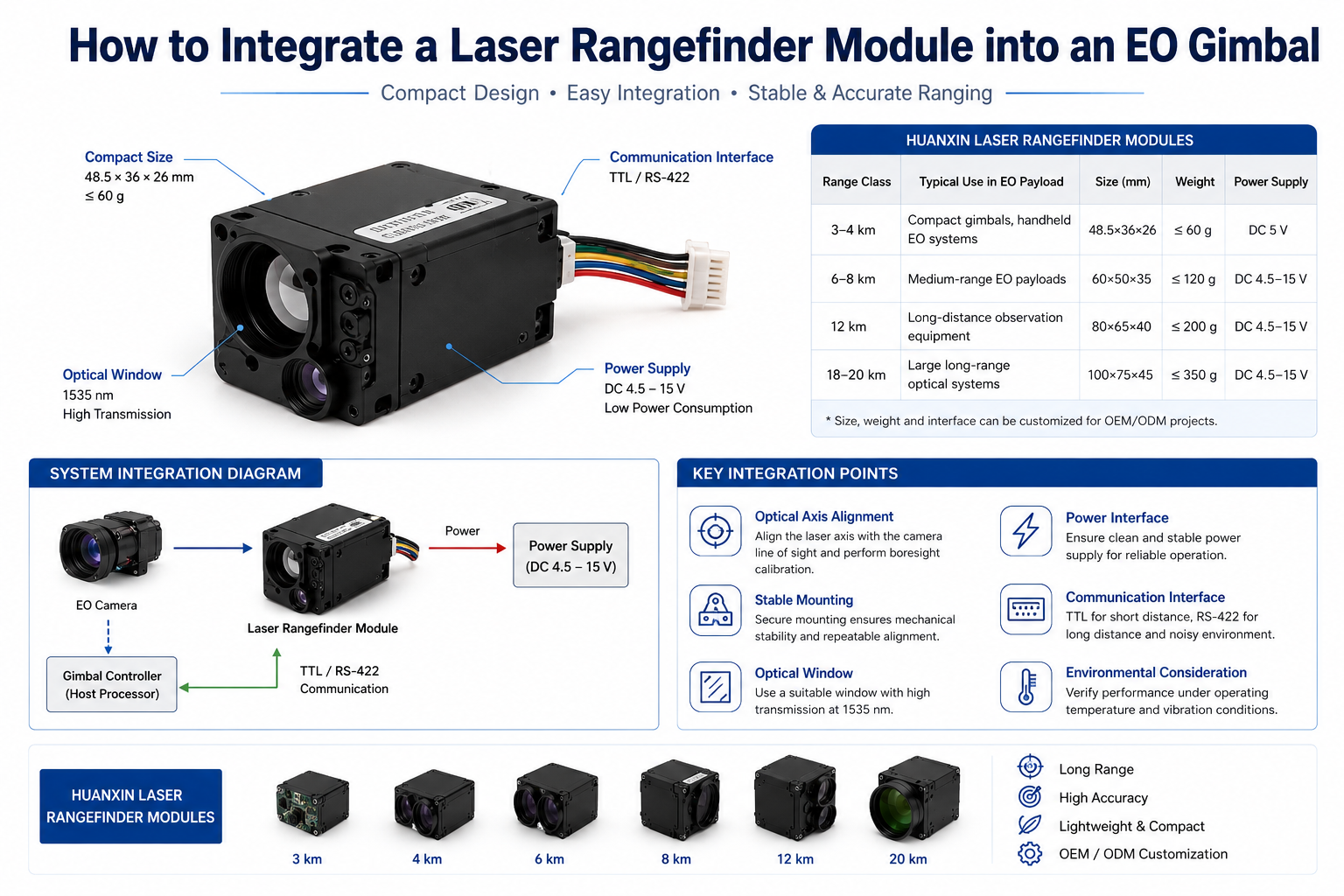
Huanxin Measurement & Control Technology Co., Ltd. manufactures 1535 nm laser rangefinder modules for OEM optical equipment. Available distance classes cover 3 km to 20 km, with compact options for smaller EO payloads and longer-range units for larger optical systems. TTL, RS-422, connectors, electrical configurations, mechanical details, and selected optical requirements can also be adapted for customer projects.
Laser Rangefinder Module Integration Starts with the EO Payload
Do not start by asking, “Should I buy the 8 km unit or the 12 km unit?”
Start with the payload.
How large is the gimbal? What cameras are already installed? How much mass can the pitch assembly carry? What voltage is available? Where is the center of gravity? Will the laser share a front window with another sensor? What type of target will normally be measured?
Those questions tell you far more than the range label alone.
A small EO head that mainly measures vehicles or buildings at a few kilometers may be better served by a compact 3 km or 4 km unit. Installing a much larger rangefinder simply because it has a higher distance rating can increase weight, power demand, and packaging difficulty without giving the operator much practical benefit.
Choose a Laser Rangefinder for EO Gimbal Use from the Real Target
Maximum ranging distance depends heavily on the target and atmosphere.
A broad concrete wall is much easier to range than a small dark object at the same distance. Target reflectivity, target angle, visibility, haze, beam divergence, receiver performance, optical alignment, and window transmission all affect the amount of useful return signal reaching the receiver.
Before selecting a laser rangefinder for EO gimbal use, define three distances:
the normal working distance;
the farthest distance that is actually required;
the minimum distance that may occur during operation.
Then describe the target size and surface.
A simple range-class guide can help narrow the choice:
These categories are useful starting points rather than guaranteed field distances. The actual target and operating environment still matter.
Match the Laser Rangefinder Module for EO Payload Size and Balance
Inside a gimbal, component weight is only part of the story. Position matters too.
Imagine holding a small weight close to your wrist and then holding the same weight at the end of a long stick. The mass has not changed, but the effort needed to move it has.
The same thing happens around a gimbal axis.
Placing the LRF close to the pitch axis usually makes balancing easier and reduces motor load. Putting it far forward or far to one side can increase torque and make stabilization more difficult.
Huanxin's compact 3K-193, at 48.5 × 36 × 26 mm and no more than 60 g, is one option for payloads where space and weight are tight.
The complete gimbal should be balanced with the actual cameras, cables, window, covers, fasteners, and rangefinder installed. Balancing an unfinished inner frame can give a misleading picture of the finished payload.
Leave Enough Space Around the LRF
A CAD drawing can make an enclosure look more spacious than it really is.
Connectors need room. Cables need bend radius. Screws need tool access. Alignment hardware may need adjustment. A rangefinder packed tightly between two other components can be difficult to install and even harder to replace later.
Leave a small service area around the unit whenever the enclosure allows it.
That extra space may look unnecessary on screen, but assembly technicians usually appreciate it.
Mechanical Planning for Laser Rangefinder Gimbal Integration
The mounting bracket links the laser axis to the gimbal structure.
If the bracket moves, the laser moves.
At short distance, a tiny angular shift may not look serious. Several kilometers away, that same shift can move the laser spot well outside the area shown by the camera crosshair.
A good mounting surface should be flat, repeatable, and stiff enough for the payload. Avoid pulling the rangefinder into position with uneven screw pressure. The housing should sit naturally against its mounting reference.
Laser Rangefinder Mounting Should Be Repeatable
Good laser rangefinder mounting is not only about keeping the unit from falling out of the payload.
The position should also be repeatable.
A machined shoulder, locating surface, controlled shim position, or similar feature can give the assembly team a clear mechanical reference.
This becomes even more valuable when a rangefinder needs to be removed for servicing. If the replacement unit returns to almost the same mechanical position, less boresight correction may be required.
Bracket Stiffness Matters More at Long Distance
A very thin bracket saves weight but may flex. A heavy block is rigid but wastes payload capacity.
A better solution is usually a short, stiff load path with enough material around the mounting points.
Temperature also deserves attention. Different materials expand by different amounts. If the rangefinder bracket and surrounding frame move differently as temperature changes, the optical axis may move with them.
For long-distance EO equipment, small mechanical changes can become visible pointing errors.
Laser Rangefinder Optical Axis Alignment Inside an EO Gimbal
A rangefinder does not need to sit directly behind the center of the camera lens.
It does need a known angular relationship with the camera.
This is the heart of laser rangefinder optical axis alignment.
Picture two flashlights taped together. If they point only slightly apart, their spots may look almost identical on a nearby wall. Move the wall several kilometers away and those two directions are no longer close.
Laser Rangefinder Module Integration Needs One Clear Sight Reference
Before alignment begins, decide which optical channel acts as the main reference.
It could be the daylight camera crosshair. It could be the thermal channel. Some systems use a defined mechanical line through the gimbal.
Pick one and document it.
The LRF pitch and yaw offset should then be recorded relative to that reference. Keep axis names, positive directions, and angular units consistent between mechanical drawings and control software.
Many annoying alignment faults come from something surprisingly simple: the hardware uses one coordinate convention while the software uses another.
Laser Rangefinder Boresight Alignment Connects the Laser to the Crosshair
Laser rangefinder boresight alignment defines where the laser is pointing compared with the displayed sight line.
A small fixed offset can usually be handled electronically.
A moving offset is a different story.
If the boresight changes after vibration, fast gimbal movement, or temperature changes, check the physical structure first. Look at bracket stiffness, mounting references, screw preload, window movement, and housing distortion.
Software can compensate for a stable angular offset. It cannot make a moving bracket stay still.
Do Fine Boresight Work Late in the Assembly
Rough alignment can be done while the payload is being built.
Fine alignment is better done after the cameras, LRF, front window, main covers, and final bracket are installed.
Adding structural parts later can slightly change the geometry. Aligning too early often means doing the work again.
For production units, record the mechanical adjustment position and stored electronic offset for each assembled payload.
The Front Window Is Part of the Laser Path
The front window is easy to underestimate.
A material that looks perfectly clear to the human eye does not automatically have the right transmission around 1535 nm. The coating, thickness, angle, clear aperture, and internal reflections can also influence ranging.
Treat the window as an optical component rather than a simple protective cover.
When possible, draw the outgoing and receiving optical paths through the window during the mechanical layout stage.
Do not draw only one centerline. Give the transmit and receive apertures realistic keep-out areas.
That makes it much easier to see whether a bracket, camera barrel, window edge, seal, or other component may enter the optical path.
Laser Rangefinder Power Interface Planning
The laser rangefinder power interface needs more attention than matching the voltage printed on a specification sheet.
Check the available voltage range, startup behavior, peak demand, connector rating, cable loss, grounding, and what happens to the rail when the gimbal motors accelerate.
Why does this matter?
Because the LRF does not operate alone.
Inside the same payload, you may have motor drivers, DC-DC converters, cameras, processors, heaters, and communication boards. The power rail can be much less peaceful inside a moving gimbal than it is on a laboratory bench.
Keep Motor Power Away from Sensitive LRF Wiring
Where the structure allows it, avoid routing sensitive LRF wiring directly beside high-current motor cables.
Use a sensible grounding arrangement and provide adequate local power conditioning.
Do not judge the required supply only from idle consumption. The load during laser firing or continuous ranging may be different.
Huanxin modules use different voltage ranges across the 3–20 km product family, so choosing the approximate distance class early also helps the electrical team reserve a suitable power rail.
Laser Rangefinder Communication Interface: TTL or RS-422?
The laser rangefinder communication interface connects the module to the host controller.
Two common choices are TTL and RS-422.
TTL can be a clean and simple choice for short internal wiring when the host logic level is compatible and the grounding is well controlled.
RS-422 uses differential signaling. It is often more comfortable when cables are longer or pass near motors, converters, slip rings, and other electrically noisy parts.
Do not stop at “TTL” or “RS-422.”
The host team should also confirm baud rate, data format, connector pinout, TTL logic level, command structure, and grounding.
Bring Up LRF Integration on the Bench First
Good LRF integration is much easier when communication is checked before the entire EO payload is assembled.
Start with a simple host controller or PC interface.
Power the rangefinder from a controlled source. Send one ranging command. Read the distance. Try repeated ranging. Cycle the power. Disconnect and reconnect the serial line. See how the host behaves when the unit does not return a valid range.
Once this works consistently, move the same command logic into the gimbal controller.
This keeps troubleshooting focused. If the rangefinder works by itself but becomes unstable after installation, attention can shift to the harness, power rail, grounding, cable motion, or host electronics.
Integrate Laser Rangefinder into EO Gimbal Electronics
When you integrate laser rangefinder into EO gimbal electronics, decide which controller will own the ranging commands.
In a small payload, the gimbal controller may communicate directly with the LRF.
A larger EO unit may send commands through a payload computer.
Both arrangements can work. What matters is having one clear control path.
Avoid allowing several processors to send commands to the LRF at the same time unless the communication architecture has been built specifically for that behavior.
Laser Rangefinder Module Integration Also Depends on Timing
A distance number without timing information can become misleading when the gimbal is moving.
The host should know when the range command was issued and when the distance value came back.
Imagine the gimbal is tracking a moving object. Between the ranging command and the returned value, the line of sight may already have shifted slightly.
Pairing range values with a timestamp or nearby gimbal attitude helps keep the distance tied to the correct pointing direction.
This part of laser rangefinder module integration becomes increasingly important in tracking systems and fast-moving platforms.
Single-Shot and Continuous Ranging Need Different Logic
Single-shot ranging is straightforward: send a command and wait for one distance value.
Continuous ranging produces a stream.
The controller then needs to handle start commands, stop commands, missing returns, stale values, timeouts, and interrupted communication without locking up the rest of the EO payload.
Higher ranging frequency is useful only when the application actually needs faster updates.
Do not chase the highest number automatically.
OEM Laser Rangefinder Integration Should Involve the Camera Team Early
Good OEM laser rangefinder integration is easier when the mechanical, optical, electrical, and camera teams work from the same coordinate references.
The daylight camera, thermal camera, LRF, gimbal axes, and displayed crosshair all need a known relationship.
If the camera position changes late in the project, the rangefinder boresight may need to be set again.
A simple shared record can include:
daylight camera axis;
thermal camera axis;
LRF axis;
gimbal pitch and yaw references;
mounting datum;
crosshair offset;
electronic correction direction;
permitted boresight error.
This is not complicated paperwork. It simply stops different teams from using different definitions for the same line of sight.
Read Beam Divergence Together with Pointing Stability
Beam divergence tells you how the laser spot expands with distance.
A narrower beam can keep more of the emitted energy on a distant object. That sounds ideal, but there is a trade-off: the gimbal has to point accurately enough to keep that smaller spot on the target.
Think of trying to hold a small flashlight spot on a road sign from far away. A tighter beam only helps if your hand is steady enough.
The same applies to an EO payload.
Beam divergence, target size, boresight accuracy, structural movement, and gimbal jitter belong in the same conversation.
A Practical Build Order for Laser Rangefinder Module Integration
Building everything at once makes troubleshooting harder.
A staged sequence is easier to manage:
This order gives every new fault a smaller list of likely causes.
If ranging changes after the window is installed, inspect the optical path first.
If communication fails only during rapid movement, inspect power quality, cable motion, grounding, and electrical noise.
Common Laser Rangefinder Gimbal Integration Mistakes
One common mistake is selecting the longest-distance rangefinder first and trying to fit it into the gimbal later.
Start with the actual working scene instead.
Another is leaving the LRF until the rest of the internal layout is almost finished. By then, the best mounting position may already be occupied by cameras, processors, or cable routes.
The rangefinder needs both a stable mechanical reference and a clean optical path, so it deserves space early.
A third mistake is relying too heavily on electronic correction for boresight.
A fixed offset is manageable. Mechanical movement is not.
The optical window causes trouble too. A window can look completely clear and still introduce transmission loss or reflections around the laser wavelength.
Power faults can be just as deceptive. If the module works well from a bench supply but resets while the gimbal moves, do not immediately blame the serial protocol. Look at the shared power rail first.
What to Send Huanxin for OEM Laser Rangefinder Integration
The more useful information the supplier receives early, the easier it becomes to choose a suitable distance class and integration configuration.
Huanxin Measurement & Control Technology Co., Ltd. can discuss customized electrical, mechanical, communication, connector, and optical integration details for OEM equipment.
Sharing this information before the gimbal enclosure is fixed gives both the customer and rangefinder supplier far more room to solve integration issues cleanly.
Where Good EO Gimbal Integration Really Starts
A laser rangefinder works best when it is treated as part of the EO payload from the beginning, not as a box added after the cameras and electronics are already in place.
Give it a stable mounting reference. Keep the transmit and receive paths clear. Check the front window around 1535 nm. Reserve a suitable power rail. Choose TTL or RS-422 based on the real cable environment. Tie the laser axis to a clearly defined camera reference. Keep each range value associated with the right gimbal direction.
None of these tasks is especially complicated on its own. The challenge is making them work together inside one compact moving system.
When mechanical, optical, electrical, and communication details are planned together, laser rangefinder module integration becomes much easier—and the finished EO gimbal is far more likely to deliver stable, repeatable ranging in real use.
FAQs
1. What should be checked first before adding a laser rangefinder to an EO gimbal?
Start with the target, normal working distance, farthest required distance, available internal space, payload mass limit, voltage, communication interface, and optical window. These items quickly narrow the suitable LRF range class.
2. Is TTL or RS-422 better for an EO gimbal?
TTL is often suitable for short internal connections with compatible logic levels and clean grounding. RS-422 is usually a better fit when the cable is longer or runs close to motors, converters, slip rings, or other noise sources.
3. Can the LRF and camera use the same optical window?
Yes, provided the material and coating transmit the required wavelength bands and the window does not clip the laser transmit or receive paths. Window thickness, angle, reflections, and mounting position should also be checked.
4. When should laser rangefinder boresight alignment be completed?
Rough alignment can be carried out after the rangefinder bracket is installed. Fine boresight work is better done after the cameras, optical window, covers, and main mechanical structure are in their final positions.
5. Can Huanxin customize a laser rangefinder module for an EO payload?
Yes. Huanxin Measurement & Control Technology Co., Ltd. supports OEM projects and can discuss selected electrical interfaces, TTL or RS-422 communication, connectors, mechanical requirements, mounting details, and optical integration needs according to the customer's EO system.