Laser Rangefinder Beam Divergence Explained: Spot Size at 1–20 km
A beam divergence figure such as 0.3 mrad or 0.5 mrad looks tiny on a specification sheet. Once that beam travels several kilometers, the picture changes.
At 10 km, a 0.3 mrad beam can cover roughly 3 meters. A 0.5 mrad beam can reach about 5 meters across. Push the distance to 20 km and those figures become about 6 meters and 10 meters.
That is why beam divergence deserves attention when selecting a laser rangefinder module. The distance rating alone does not tell you how well the beam matches the object you want to measure.
Huanxin Measurement & Control Technology Co., Ltd. manufactures 1535 nm laser rangefinder modules covering distance classes from 3 km to 20 km. Different modules use different beam divergence values to suit their optical configuration, range class, size, and intended integration.
So, what does that small mrad number actually mean in a real optical system?
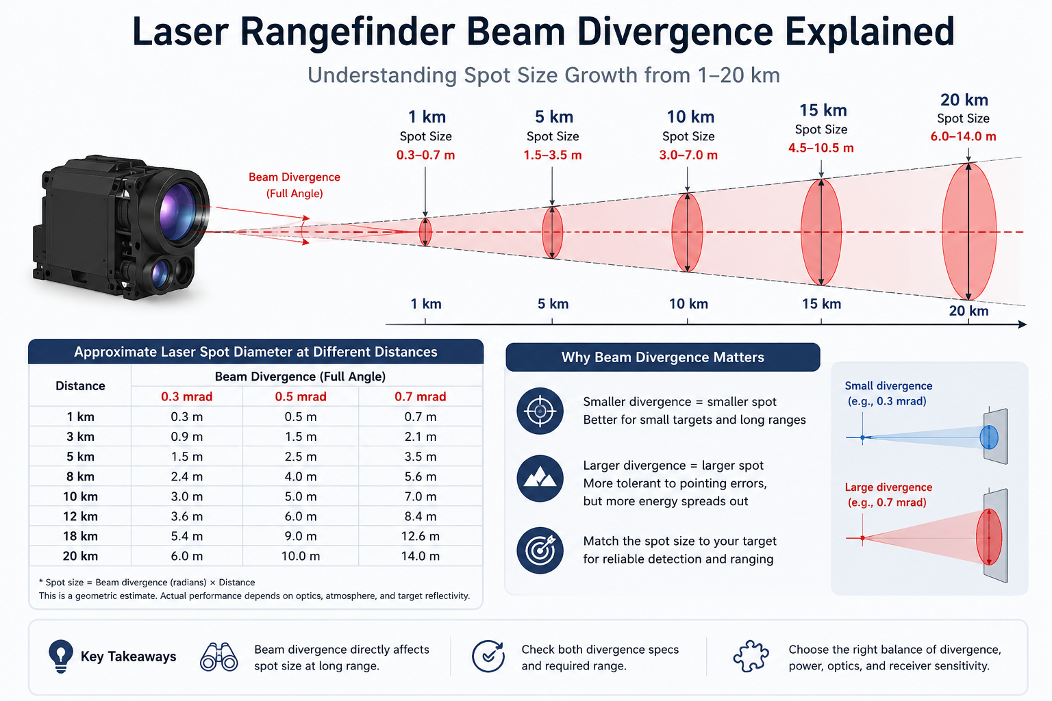
Why Laser Rangefinder Beam Divergence Matters at Long Range
A laser beam does not stay the same width from the transmitter to the target. It gradually expands as it travels.
You can picture it as a very narrow cone. Close to the laser, the cone is small. A few kilometers away, its footprint becomes much wider.
This expanding angle is usually given in milliradians, written as mrad.
A smaller number means the beam expands more slowly.
A 0.3 mrad beam stays narrower than a 0.5 mrad beam at the same distance. That sounds simple, but narrower is not automatically better. The host platform still needs to point the beam accurately enough to keep it on the target.
Reading Laser Rangefinder Beam Divergence in mrad
For long-distance optical work, mrad is convenient because the numbers convert into meters very easily.
As a quick rule:
Spot diameter in meters ≈ beam divergence in mrad × distance in kilometers
Using that relationship:
0.3 mrad × 5 km ≈ 1.5 m
0.3 mrad × 10 km ≈ 3 m
0.5 mrad × 10 km ≈ 5 m
0.5 mrad × 20 km ≈ 10 m
This is a practical first calculation rather than an exact description of every part of the optical beam.
The laser already has a finite diameter when it leaves the module. Beam shape is not perfectly uniform either. At long distances, though, divergence becomes the dominant factor, so the simple calculation is very useful.
Check Whether the Value Is Full-Angle or Half-Angle
There is one detail that engineers should confirm before calculating spot diameter.
Some suppliers specify full-angle divergence. Others may quote a half-angle value.
If you mistake one for the other, your calculated spot size can differ by roughly a factor of two.
When working with a new laser rangefinder module, confirm how divergence is defined in the specification sheet before making optical calculations.
Laser Beam Divergence Spot Size from 1 km to 20 km
The easiest way to see what divergence does is to put a few common values beside real distances.
Huanxin's current laser rangefinder module range includes beam divergence figures around 0.3 mrad, 0.5 mrad, and 0.7 mrad, depending on the module configuration. The 8K-338, 12K-4712, and 18K-4718 are listed at no more than 0.3 mrad, while the 20K-6520 is listed at no more than 0.5 mrad.
The table below shows the approximate geometric spot diameter.
The table makes one thing clear: the effect grows with distance.
At 1 km, the difference between 0.3 and 0.5 mrad is only about 20 cm in spot diameter. At 20 km, it becomes about 4 meters.
That is a much bigger engineering difference.
Why Spot Size Grows So Quickly with Distance
The beam is expanding at an angle rather than adding a fixed physical width inside the module.
Every extra kilometer gives that angle another kilometer in which to spread.
You can think of two lines starting almost parallel. At first, the space between them is tiny. Keep extending those lines and the separation becomes easy to see.
The same idea applies to a laser beam.
This is one reason long-range laser rangefinder integration needs closer attention to pointing accuracy, optical alignment, target size, and platform movement than short-range equipment.
0.3 mrad Spot Size at 10 km: What Does 3 Meters Mean?
The 0.3 mrad spot size at 10 km is roughly 3 meters across when 0.3 mrad is treated as the full beam divergence.
Three meters may sound large for a laser, but 10 km is a long optical path.
Now imagine ranging a building wall. A 3-meter spot can remain fully inside a large wall area without much difficulty.
Move to a smaller object and the situation changes.
A vehicle may only present a few meters of useful width from a particular viewing direction. If the beam approaches the same size as the visible target area, pointing becomes much more important.
A small angular shift can place part of the laser footprint outside the intended object.
A 0.3 mrad Beam at Other Long Distances
At 8 km, the rough spot diameter is about 2.4 m.
At 12 km, it is about 3.6 m.
At 18 km, it reaches about 5.4 m.
This is useful when looking at Huanxin's longer-distance modules. The 8K-338, 12K-4712, and 18K-4718 all list beam divergence of no more than 0.3 mrad.
The 18K-4718 also lists beam pointing instability of no more than 0.03 mrad. At 18 km, an angular change of 0.03 mrad corresponds to roughly 0.54 m at the target plane.
This shows why beam width and pointing behavior belong in the same conversation.
A narrow beam is useful only when the system can place it where it needs to go.
0.5 mrad Laser Spot Size at 3–20 km
A 0.5 mrad laser spot size grows by about half a meter for every kilometer of travel.
At 3 km, that works out to around 1.5 m.
At 6 km, roughly 3 m.
At 10 km, around 5 m.
At 20 km, the footprint reaches roughly 10 m.
Does a 10-meter spot make a 20 km module unsuitable?
Not necessarily.
The correct answer depends heavily on what you are measuring.
Why a Wider Beam Can Still Work at Long Range
Imagine aiming at the broad face of a building.
A 10-meter beam footprint can still land almost entirely on the building if the visible surface is large enough.
Now imagine trying to measure a narrow pole at the same distance. Only a small portion of the outgoing beam may hit it.
That difference changes the amount of useful reflected laser energy returning to the receiver.
Huanxin's 20K-6520 is a good real-world illustration. Its listed beam divergence is no more than 0.5 mrad. The page separates its ranging capability by target type: at least 17 km for a specified vehicle-sized target and at least 20 km for a building-type target under the stated atmospheric and reflectivity conditions.
The target matters just as much as the distance number.
Beam Divergence vs Target Size: Which Matters More?
When discussing beam divergence vs target size, it is better to think about how the two interact rather than trying to rank one above the other.
A beam footprint much smaller than the target gives the system more room for small pointing shifts.
A beam close to the width of the target leaves less margin.
A beam much larger than the target means more outgoing laser energy falls outside the useful surface.
Here is a simple way to think about it.
This does not mean the beam must always fit completely inside the target.
Laser ranging depends on the amount and quality of returned light. A strong reflective surface may still give a usable return even when only part of the beam lands on it.
A weak, dark, angled, or distant surface can be less forgiving.
When the Beam Is Smaller Than the Target
Suppose your beam is about 2.4 m across at 8 km and the target is a large wall.
Most or all of the laser footprint can land on the wall.
A small pointing shift may still leave the beam on the same surface. This makes the optical geometry easier to manage.
When the Beam Is Larger Than the Target
Now suppose the target is only 2 m wide and the beam footprint is 5 m.
A large share of the beam can miss the object.
If there is another surface behind the target, part of the outgoing beam may illuminate that surface too. The receiver may then see returns from more than one distance.
The exact behavior depends on the ranging electronics and scene geometry, but this is why background objects deserve attention when the beam becomes larger than the intended target.
Target Shape Matters Too
Width and height alone do not tell the whole story.
A wall facing the rangefinder offers a broad surface.
A vehicle may present curved panels, windows, dark sections, and edges.
A target viewed at a shallow angle can offer much less useful reflecting area than the same object viewed straight on.
So when estimating spot size, think about the visible surface seen from the laser's actual line of sight.
Laser Rangefinder Beam Divergence and Pointing Error
Beam spread is only one angular value inside the system.
The host platform also has pointing accuracy. The laser axis may have alignment tolerance relative to the camera. Mechanical vibration can move the line of sight. Temperature can shift optical or mechanical parts slightly.
At long range, even tiny angular movement becomes visible at the target.
A 0.1 mrad pointing shift corresponds to roughly:
0.5 m at 5 km
1 m at 10 km
1.5 m at 15 km
2 m at 20 km
This means a narrow laser beam does not automatically guarantee that more energy lands on the intended object.
If the host cannot hold the beam accurately, the optical advantage of low divergence can shrink quickly.
Why the Narrowest Beam Is Not Always the Best Choice
It is easy to look at two modules and assume 0.3 mrad must be better than 0.5 mrad.
That is too simple.
A narrower beam keeps the laser energy inside a smaller angular area. This can be useful for long-distance ranging.
It also gives the system less tolerance for pointing movement.
A slightly wider beam may be easier to keep on a moving or imperfectly tracked target.
The best value depends on target dimensions, range, emitted energy, receiver sensitivity, platform stability, optical alignment, and the working environment.
There is no single beam divergence value that fits every laser rangefinder.
How Atmosphere Changes the Real Ranging Situation
Spot-size calculations assume simple geometry. Real outdoor ranging adds another layer: the atmosphere.
The laser pulse travels from the rangefinder to the target and then the reflected light has to travel back.
That path may include haze, humidity, dust, rain, turbulence, or heat shimmer.
At 15 or 20 km, the total optical path is long enough that atmospheric conditions can have a noticeable effect on the returned signal.
This is why maximum measuring range should never be treated as a standalone number.
Huanxin's current product pages tie distance ratings to stated conditions such as visibility, humidity, target size, reflectivity, terrain, or flight altitude, depending on the module.
Reflectivity Changes How Much Light Comes Back
A bright, diffuse surface often gives the receiver more usable returned energy than a dark surface.
Highly angled surfaces can send much of the reflected light away from the receiving optics.
Glass can behave differently again because it may transmit, reflect, or create unwanted returns depending on angle and coating.
Beam divergence tells you how large an area is illuminated.
It cannot tell you by itself how much light will return.
Laser Rangefinder Beam Divergence in Huanxin Modules
Huanxin provides several beam divergence configurations across its 1535 nm laser rangefinder module family.
These figures also show why ranging distance should not be predicted from divergence alone.
The 20 km unit does not need to use the smallest divergence figure in the product family. Its optical power, receiver, target conditions, physical size, and intended long-range operating scene are different from those of the compact modules.
Choosing Beam Divergence for an OEM Laser Rangefinder Module
If you are selecting a laser rangefinder module for integration, start with the actual target rather than saying only, “I need 10 km” or “I need 20 km.”
The supplier needs to understand what the laser will see at that distance.
A useful project description might say:
“I need to measure vehicle-sized objects at 8 km, with most targets between 4 and 6 meters long, from a stabilized EO platform.”
That is much more useful than a distance number alone.
What to Check Before Selecting the Module
Before choosing a beam configuration, collect the following information:
Once these details are known, beam divergence becomes much easier to judge.
A Fast Spot-Size Check Before You Request a Quote
You can make a useful first check in less than a minute.
Take the divergence in mrad.
Multiply it by your farthest operating distance in kilometers.
Then compare the number with the approximate visible size of your target.
Say the target is around 4 m wide at 10 km.
A 0.3 mrad beam gives an estimated 3 m footprint.
A 0.5 mrad beam gives around 5 m.
Neither number alone tells you which module to buy, but now you have a much clearer picture of the optical geometry.
Next, consider pointing movement, reflectivity, atmospheric visibility, receiver characteristics, window loss, and available installation space.
That is a far better way to select a module than choosing the largest distance number on a product page.
A Practical Takeaway for Long-Range Ranging
Laser rangefinder beam divergence looks like a small specification, but distance magnifies its effect quickly. A 0.3 mrad beam is roughly 3 m across at 10 km and 6 m at 20 km. A 0.5 mrad beam reaches about 5 m at 10 km and 10 m at 20 km.
The right value depends on where that spot lands and how much of the intended object it covers. Target size, surface, pointing stability, platform motion, atmosphere, receiver performance, and optical alignment all play a part.
Huanxin Measurement & Control Technology Co., Ltd. manufactures 1535 nm laser rangefinder modules from 3 km to 20 km and can provide customized configurations for OEM integration. If your project has a specific target size, working distance, interface, voltage, space, or optical-window requirement, sharing those details early makes it much easier to select a suitable module.
FAQs About Laser Rangefinder Beam Divergence
1. How large is a 0.3 mrad laser beam at 10 km?
If 0.3 mrad is the full-angle divergence, the approximate spot diameter is 3 meters at 10 km. The actual beam footprint can differ slightly because of the exit beam diameter and optical characteristics.
2. What is the 0.5 mrad laser spot size at 20 km?
A 0.5 mrad beam gives an approximate geometric spot diameter of 10 meters at 20 km. Whether that is suitable depends heavily on target size and pointing accuracy.
3. Is 0.3 mrad better than 0.5 mrad for a laser rangefinder?
Not in every system. A 0.3 mrad beam stays narrower and can concentrate outgoing laser energy over a smaller area. It also requires tighter pointing. A 0.5 mrad beam may suit systems where the target is large or where a little more angular tolerance is useful.
4. Does laser beam divergence determine maximum ranging distance?
No. Beam divergence is only one part of long-range performance. Laser energy, receiver sensitivity, aperture, target reflectivity, target dimensions, visibility, alignment, optical-window transmission, and platform behavior also affect usable range.
5. Should the laser spot always be smaller than the target?
Not always, but keeping a large share of the beam on the intended target is usually helpful. If the spot becomes much larger than the target, more outgoing energy misses the useful surface and nearby objects may also enter the illuminated area.