Boresighting a Laser Rangefinder with Thermal/Daylight Cameras: Methods & Tools
You lock a high-definition thermal crosshair onto a small vehicle cab three kilometers out, click the range trigger, and watch the read-out flash zero or jump three hundred meters past the silhouette. The transceiver fired cleanly, but the invisible pulse sailed wide, striking an open ditch behind your target. When your line of sight drifts away from your pulse vector, even the most expensive multi-sensor payload fails its core task.
Co-aligning multi-spectral sensors demands extreme mechanical discipline. You must merge a high-magnification visible channel (400–700 nm), an uncooled or cooled thermal sensor (8–14 μm LWIR / 3–5 μm MWIR), and a 1535nm eye-safe laser pulse onto the exact same surface patch. Let’s walk through the mechanics, optical tools, and field routines that keep boresighting laser rangefinder channels locked dead-center across long ranges.
WhateThe Physics of Seeing Together: Coaxial Alignment EO/IR Payloads
Every sensor mounted inside a stabilized turret operates within its own optical domain:
Daylight cameras collect reflected ambient photons.
Thermal imagers detect radiated heat emitted by target materials.
Laser rangefinders (LRFs) emit narrow nanosecond pulses and read time-of-flight returns.
True coaxial alignment EO/IR integration ensures that the central optical axis of each imaging channel runs entirely parallel to the pulse emission vector of the LRF. When aligned, your thermal crosshair, your daylight zoom reticle, and the centroid of your laser beam strike the identical point in three-dimensional space.
Why Pinpoint Boresighting Laser Rangefinder Modules Dictates Mission Success
A laser beam does not travel as an infinitely sharp needle. It expands along its specified divergence angle:
If mechanical misalignment reaches just 1 milliradian—a tilt completely invisible to the human eye on an assembly jig—your energy center lands three to five meters away from your visual reticle at distance. That pulse bypasses the vehicle chassis and bounces off surrounding terrain.
Narrow Beams vs. Wide Sensor Fields of View
When optical zoom lenses pinch the field of view down to two or three degrees, any residual angular tilt between the sensor mounts gets magnified on screen. The physical mounting platform must stay structurally rigid to prevent the laser footprint from drifting off the digital aiming crosshair under heavy flight or road vibration.
Unmasking Geometric Offset: Parallactic Error Correction Laser Rangefinder Systems
Physical apertures cannot occupy the identical spot on a turret faceplate. They sit separated by a baseline distance ($B$), usually 50 to 100 millimeters apart. This creates parallax. When setting up parallactic error correction laser rangefinder mechanics, system integrators choose between two foundational approaches:
Calculating the Parallax Offset Across Variable Targets
Imagine an aperture offset of 70 millimeters. Under a parallel setup, the beam strikes 70 millimeters to the right of the thermal reticle at 50 meters, and still exactly 70 millimeters to the right at 3,000 meters. At three kilometers, that 70-millimeter shift is completely absorbed inside a 1.5-meter laser footprint.
Angling axes inward to converge at 200 meters solves close-range target offset. But pass that 200-meter crossover point, and the beam diverges outward to the opposite side. At two kilometers, this angular divergence pushes the beam several meters away from your reticle center, causing catastrophic misses.
Near-Field Separation vs. Far-Field Convergence
For long-distance observation platforms, parallel alignment remains standard. Dynamic reticle shifting handles close-range shots: the LRF pings the range, feeds the value to the onboard video tracker, and system software translates the reticle by a few pixels on screen to compensate for aperture spacing.
Step-by-Step Execution: How to Boresight LRF with Thermal Camera Channels
Field teams often ask how to boresight LRF with thermal camera channels when human eyes cannot see 1535nm short-wave pulses or long-wave heat energy. You need tools that translate invisible emissions into visible pixel references simultaneously:
Sensitizing the Invisible: Thermal Conversion Screens and Active Burn Paper
A reliable field approach pairs a thermal target face with an optical laser conversion screen. Technicians machine a precision crosshair slot into a temperature-controlled aluminum plate. An infrared sensor card or SWIR camera sits directly behind the aperture. The thermal imager locks its digital crosshair onto the crisp heat edges of the heated cutout. When the rangefinder fires, the conversion plate displays the pulse spot, letting technicians match beam placement against the thermal crosshair.
Capturing the 1535nm Er:Glass Pulse Signature
Standard silicon cameras lose sensitivity above 1100 nanometers. Capturing 1535nm eye-safe pulses requires an Indium Gallium Arsenide (InGaAs) detector array or specialized up-conversion phosphor plates that emit visible light when excited by short-wave infrared energy.
Essential Hardware: Deploying a Coaxial Boresight Target System
Production facilities depend on a dedicated coaxial boresight target system to strip out guesswork and provide repeatable multi-band target points on one fixture.
Thermal Crosshairs and Reflective Optical Patterns
Advanced alignment panels combine polished low-emissivity aluminum patterns with high-emissivity matte coatings. Integrated thermoelectric Peltier elements warm the panel, producing a clean thermal outline on the infrared channel. Concentric visual rings provide a daylight alignment mark, while a retroreflective core sits at the center to bounce rangefinder pulses straight back into the transceiver.
Outdoor Multi-Band Targets for Harsh Testing Environments
Verifying mobile installations on vehicle mounts or patrol boats requires outdoor ranges from 500 meters to two kilometers. Mobile targets use high-draw battery packs and weather-sealed heating coils to keep target faces flat, stable, and visible through wind and solar glare.
Laboratory Setup: A Comprehensive Laser Rangefinder Optical Axis Alignment Guide
Outdoor test paths suffer from ground shimmering, rising heat plumes, and wind drift. Indoor cleanrooms follow an established laser rangefinder optical axis alignment guide centered on reflective optical collimators.
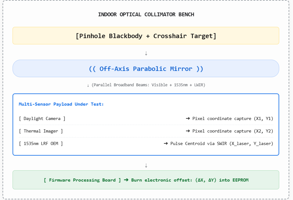
Off-Axis Parabolic Collimator Systems
Standard glass lenses refract light wavelengths at different angles, creating severe chromatic aberration. A glass lens focused on daylight will blur 1535nm pulses and thermal wavelengths completely out of focus.
Reflective collimators solve this through front-surface mirrors coated in gold or protected aluminum. Because rays reflect rather than refract through glass, all wavelengths share the exact same focal point. Placing an illuminated pinhole target at the mirror's focus projects parallel light directly into your sensors, simulating a target at infinite distance inside a compact two-meter workspace.
Digital Reticle Calibrations via Electronic Offsets
Modern gimbals skip manual brass adjustment screws. Once the optical chassis is bolted in place, the LRF fires down its mechanical axis. Technicians identify the laser spot centroid on the collimator camera, move the thermal and visual reticles onto that coordinate, and save those offsets straight into non-volatile memory.
Environmental Drift: Maintaining Mechanical Stability Across Extreme Thermal Cycles
A multi-sensor payload aligned inside an air-conditioned room faces brutal environments on duty, enduring -40°C patrol altitudes or 60°C desert heat. Uneven thermal expansion between mismatched chassis metals warps optical alignment over time:
OEM Integration Engineering by Huanxin Measurement & Control Technology
Preventing boresight drift requires thermally stable, rugged internal components. As a dedicated manufacturer of Laser Rangefinder Modules, Huanxin Measurement & Control Technology produces compact optical engines tailored for demanding multi-sensor assemblies.
Huanxin’s 1535nm Erbium-glass modules feature structural chassis engineered to match the expansion profiles of aircraft-grade aluminum and titanium frames. Balancing the optical mounting geometry prevents internal pump diodes, laser glass elements, and transmitter optics from warping out of alignment between -40°C and +65°C.
Custom Tailoring for UAV Gimbals and Handheld Reconnaissance
Different payloads bring unique structural envelopes, from four-inch micro-gimbals to stabilized naval pan-tilt heads. Huanxin supplies custom mechanical mounting flanges, precision alignment dowel pin channels, and clean serial interfaces (RS-422, TTL). Machined reference surfaces ensure modules slide into multi-sensor assemblies with factory parallelism within 0.3 milliradians before digital calibration even begins.
The Final Verification Check: Knife-Edge Scanning
Before clearing a payload for field deployment, execute a knife-edge boundary sweep:
Step 1: Locate a crisp vertical structure (concrete building edge / metal beam) with open background.
Step 2: Place the reticle 5 pixels left of the edge (Aiming into open background space).
Step 3: Fire continuous pulses -> Rangefinder must return the distant background range.
Step 4: Micro-step the reticle across the boundary onto the physical structure.
Step 5: Check range switch -> Reading must snap immediately to the foreground distance.
If the range reading shifts before the crosshair touches the physical edge, your boresight is off. If it snaps cleanly right as the reticle crosses the structural boundary, your lines of sight are locked, calibrated, and mission-ready.
FAQs
What mechanical factors cause sensor boresights to drift over time?
Drift stems from structural shock, persistent motor vibration in aerial gimbals, and uneven thermal expansion rates across mixed chassis metals. Securing assemblies with hardened locating pins, thread-locking compounds, and matched alloy enclosures prevents drift under heavy use.
Can a visible red laser pointer co-align a 1535nm rangefinder?
Only for rough initial positioning. Visible red light and 1535nm infrared travel along different optical paths and refract differently through lenses. Final calibration requires capturing the true 1535nm pulse footprint using a SWIR camera or beam conversion screen.
What angular tolerance is required for long-range targeting payloads?
Systems targeting past three kilometers require total axis alignment errors below 0.2 to 0.3 milliradians. Any angular offset exceeding 0.5 milliradians risks missing compact vehicles or structures completely.
Why do alignment laboratories use off-axis parabolic mirrors instead of glass lenses?
Parabolic mirrors rely purely on front-surface reflection rather than refraction. Because light reflects without passing through glass media, visible colors, short-wave infrared, and long-wave thermal bands share the exact same focal point without chromatic dispersion.
How do custom mounting surfaces simplify factory integration?
Factory-machined mounting faces and dowel channels align the rangefinder module's optical axis with its mechanical casing. This physical alignment allows modules to drop straight into gimbal structures with sub-milliradian accuracy, minimizing manual shimming during assembly.