Integrating a Laser Rangefinder Module into Drone & UAV Gimbal Payloads: A Complete OEM Guide
Ever opened up a three-axis drone turret and wondered where the rest of your hardware is supposed to live? It is tight in there. You have high-res optical blocks, cooled thermal cores, video processing boards, brushless motors, and an absolute nest of flexible cables all fighting over the same cubic centimeters.
Gimbal engineering is brutal because every extra gram steals flight time, and every millimeter off-center makes your stabilization motors sweat. Yet, if you want your airframe to do more than just stream pretty aerial video, you need real distance data. Slapping a laser onto an existing camera pod sounds simple enough on paper, but turning that concept into a clean, flight-ready payload takes deliberate engineering. Let's break down how payload developers pull off this hardware marriage without blowing their weight limits or throwing off their camera balance.
The Rise of Precision Ranging in Modern Aerial Systems
Years ago, aerial spotters were happy just getting high-definition live video feeds down to a field monitor. You found the target, watched it, and made an educated guess about its physical coordinates based on flight altitude and camera tilt. That sort of guesswork burns fuel and leads to embarrassing navigation mistakes.
Why Modern Aerial Sensors Demand Distance Measurement
Video by itself is flat. A high-zoom camera can show you a parked utility truck, but it cannot tell you if that truck sits 800 meters out in a clearing or three kilometers away on an opposing ridge. Tucking a UAV laser rangefinder module right next to your daylight sensor fixes that blind spot. The sensor shoots high-speed pulses at the target, clocks the flight time, and returns an exact millimetric slant range. Feed that return into your flight computer alongside telemetry and GPS data, and your platform tags real-world UTM or MGRS coordinates onto your screen immediately.
How Compact 1535nm Rangefinder for FPV Drone Surveillance Changes Tactical Operations
Compact, high-speed aircraft have migrated out of the hobbyist park and straight into industrial and security arenas. Pilots operate these nimble airframes in tight spaces where survival means keeping a low profile. Running a compact 1535nm rangefinder for FPV drone surveillance flips the script on traditional reconnaissance. Because the 1535nm band stays invisible to ordinary image-intensifier night vision goggles, your crew can ping positions three kilometers away without broadcasting an obvious bright beacon. Plus, it is eye-safe, meaning you can train with it or run utility checks in populated areas without safety crews sweating laser hazards.
Selecting the Best Laser Rangefinder Module for UAV Gimbal Payload Needs
Compact 1535nm UAV Laser Rangefinder Module
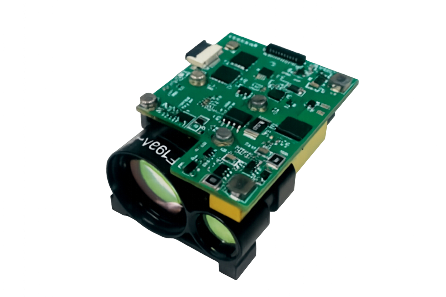 Figure 1: Bare-board dual-aperture OEM flight configuration
Every drone has hard physical limits. Picking the best laser rangefinder module for uav gimbal payload designs is a balancing act between reach, beam quality, current draw, and raw mass. Pick a bulky industrial rangefinder, and you will turn your agile gimbal into an unresponsive, overheating brick.
Wavelength Decisions: 905nm Versus 1535nm Erbium Glass
Most drone builds come down to two competing laser wavelengths: 905nm semiconductor diodes or 1535nm erbium-glass emitters. A 905nm module is cheap, tiny, and works fine for close-up aerial surveying or hobbyist altitudes under a kilometer. If your craft flies high-altitude maritime scans, perimeter patrols, or long-range border runs, 1535nm is the undisputed king.
Here is a quick look at how these two laser technologies stack up inside an aerial turret:
Atmospheric Penetration Through Haze, Smoke, and Moisture
Air is full of junk. Dust, humidity, heat shimmers, and marine mist scatter short-wavelength laser beams in every direction. At 905nm, that beam spreads out, reflects off nearby water droplets, and drowns the return photodiode in clutter. Light at 1535nm cuts straight through those microscopic water pockets, keeping the pulse tight and punching back a crisp signal when weather turns nasty.
Eye Safety Ratings and Covert Operational Advantages
The human eye's front cornea absorbs 1535nm radiation before it hits the delicate retina. Because of that natural barrier, laser safety standards allow you to fire much higher peak power pulses without endangering eyes on the ground. You get massive range and high signal-to-noise ratios, all while flying under strict eye-safety guidelines. That is why commercial power line inspectors and tactical teams alike insist on 1535nm hardware.
Picking a Lightweight Laser Rangefinder Module Under 100g
Gimbal motors despise front-heavy camera bays. Sourcing a lightweight laser rangefinder module under 100g protects your pitch motor from working overtime. Huanxin Measurement & Control Technology builds ultra-compact OEM ranging units tailored for tight aerial shells. Our micro-footprint modules register around 55 to 60 grams on the scale, yet they comfortably deliver reliable returns past 3,000 meters. Keeping the core hardware featherweight leaves you breathing room for beefier lenses, thicker shielding, or bigger battery packs.
Mechanical Packaging and Payload Mass Distribution
Stuffing electro-optics into a spherical ball is an exercise in compromise. A motorized gimbal works because its axes balance on a razor's edge. Throw off that mechanical balance, and you will deal with horizon drift, persistent frame buzz, and burnt-out motor driver chips.
Gimbal Axis Torque and Inertia Considerations
Take a full water bottle and hold it against your ribs; it feels effortless. Stretch that same arm straight out for five minutes, and your shoulder starts shaking. That exact lever-arm principle applies inside a drone turret. If you mount a drone gimbal rangefinder out toward the edge of your sensor carrier, its rotational inertia multiplies rapidly. Every wind gust forces the stabilization motors to slam high torque into the system just to stay on target. Keep your laser sensor as close as physically possible to the rotational intersection where the tilt and pan axes cross. Low rotational inertia keeps motor draw low and stabilizes your 30x optical zoom.
Thermal Dissipation and Structural Isolation Inside Tight Enclosures
Rangefinders do not get as hot as video encoder chips, but their internal laser cavities hate sudden temperature jumps. An uncooled, airtight gimbal shell acts like a miniature greenhouse when flying under baking summer sun. Bolt your compact OEM laser rangefinder directly to an aluminum bulkhead that carries heat out to the external skin. Watch out for mounting torque, too. If you mount a bare module to an uneven chassis face and wrench down the screws, you will twist the precision aluminum housing just enough to pull the internal emitter out of focus. Flat mounting faces and proper torque wrenches are non-negotiable.
Integrating LRF Module with Drone Optical Camera Arrays
A rangefinder is worthless if it pings a barn roof when your camera reticle sits on the front door. Aligning multiple optical lines inside an aerial payload requires smart glass choices and patient mechanical tuning.
Optical Window Selection and Anti-Reflective Coatings
Never shoot a laser pulse through cheap plastic or standard camera glass. Regular glass surfaces bounce back a tiny percentage of the outgoing flash straight into your receiving optics. That tiny reflection floods the ultra-sensitive APD receiver and spits out a false zero-meter reading. When integrating lrf module with drone optical camera payloads, build in dedicated optical-grade fused quartz or sapphire flat windows. Ensure both sides feature multi-layer anti-reflective coatings dialed to your exact wavelength (such as 1535nm). Leave generous clear aperture around the exit beam, too; you do not want your beam scraping the metal bezel when the airframe flexes.
Precision Boresighting and Mechanical Axis Alignment
A laser beam is not a parallel line; it expands over distance based on its beam divergence. A clean 0.5 mrad divergence yields roughly a half-meter spot at 1,000 meters. If your mechanical bracket sits just 0.1 degrees crooked, that laser spot drifts completely outside your camera's digital reticle at operational distances.
Payload builders generally pick between three ways to handle boresighting:
Whichever path you choose, only run your fine optical alignment after your cameras, slip rings, and wire bundles are fully tied down. Tightening down an adjacent circuit board often introduces micro-flex into the chassis, pulling your boresight out of true before the drone even takes off.
Electrical Architecture, Power Conditioning, and Serial Protocols
Bad power feeds and dirty data lines ruin sensor performance faster than mechanical flaws. Pulsed lasers draw sudden, intense bursts of power during discharge. If your electrical layout cannot handle those fast pulses, you are going to see glitches across your entire system.
Signal Routing: Comparing TTL and RS-422 for Moving Gimbals
Carrying telemetry across continuous-rotation slip rings is a classic engineering trap. A standard 3.3V or 5V TTL UART connection is fine if your flight controller sits two inches away on the same stationary board. Run that low-voltage line down through a rotating slip ring next to high-current PWM motor wires, and electromagnetic noise will chew up your data packets. Moving your serial communication to differential RS-422 solves the problem completely. The two-wire balanced signal shrugs off motor interference, keeping your range readouts smooth and uninterrupted while the gimbal snaps through high-speed sweeps.
Peak Firing Current and Power Rail Decoupling
A resting compact OEM laser rangefinder sips barely any current. The instant you hit the continuous ranging trigger, that laser pump demands heavy peak current for nanoseconds at a time. If your payload power supply shares a thin circuit rail with your delicate camera core without isolation, that sudden current dip drops the local voltage rail. You will see it instantly: camera artifacts, video flickering, or random microcontroller reboot loops. Place dedicated low-ESR ceramic and tantalum bypass capacitors right at the power input pins of your ranging module to buffer those rapid transient spikes.
OEM Custom Solutions by Huanxin Measurement & Control Technology
Off-the-shelf catalog sensors rarely drop into custom drone gimbals without headaches. Every payload bay has its own odd corners, structural ribs, and proprietary flight bus protocols. That is why working with a true hardware manufacturer pays dividends.
Tailored Form Factors and Specialized Firmware
At Huanxin Measurement & Control Technology Co., Ltd., we build high-precision 1535nm and 905nm laser rangefinder modules engineered to meet strict size, weight, and power demands. We do not just hand you a standard box and wish you luck. Our engineering team routinely customizes chassis geometries, relocates optical emission centers, modifies mounting hole patterns, and rewires connector headers to slip neatly into your mechanical envelope. If your autopilot software demands a custom binary packet structure or specific baud rates, our software developers modify internal firmware to get your communications working out of the box.
Comprehensive Testing Across Severe Thermal Profiles
A sensor that runs fine on an office workbench can fall apart when flying at 10,000 feet in freezing winds or hanging over a baking desert tarmac. Every drone gimbal rangefinder that rolls out of our facility undergoes exhaustive thermal stress testing and shock validation. Our optics stay aligned and our detectors stay tuned across punishing temperature ranges from -40°C all the way to +60°C. When your drone takes off in rough conditions, our hardware holds its calibration and delivers the clean ranging data your operators count on.
Elevating Next-Generation Airborne Payloads
Adding a laser ranging sensor is the single biggest upgrade you can make to a modern drone gimbal. It turns a passive video monitor into a precise geospatial locator. Building a high-performance system comes down to respecting the fundamentals: pick an eye-safe, haze-cutting 1535nm wavelength, keep overall mass low, protect your optical windows from stray back-scatter, and shield your serial lines from motor noise. Get those details dialed in, and your gimbal will lock on, measure true, and give your flight crews the situational awareness they need to get the job done right.
FAQ
Why choose a 1535nm laser rangefinder module over a 905nm module for drone payloads?
The 1535nm band is truly human-eye-safe at much higher energy levels, allowing you to ping targets several kilometers farther than 905nm units. It cuts cleanly through dust, mist, and atmospheric haze without scattering. It also remains completely invisible to standard night vision gear, keeping night operations discreet.
How do I prevent laser back-scatter from ruining my payload's sensor readings?
Always fit your sensor window with optical-grade fused silica or sapphire glass treated with anti-reflective coatings matched to your laser wavelength. Leave enough physical gap between the module front and the window frame so outgoing pulses never clip the metal edges, avoiding false zero-distance readings.
Can Huanxin build custom laser rangefinder modules for weird gimbal shells?
Yes. Huanxin Measurement & Control Technology Co., Ltd. provides full OEM customization. We regularly redesign external aluminum housings, shift optical centerlines, adjust mounting lugs, build custom wiring harnesses, and rewrite communications protocols to drop right into your chassis.
Why should I run RS-422 instead of simple TTL inside my gimbal turret?
Brushless stabilization motors generate massive electromagnetic fields as they hold steady horizons. Simple single-ended TTL signals easily pick up that electrical crosstalk as they pass through payload slip rings, causing dropped packets. Differential RS-422 cancels out that electrical noise, keeping data clean.
Where is the best spot to mount a laser rangefinder module inside a spherical gimbal?
Mount it as close as possible to the intersection of the tilt and pan axes. Positioning the module near the rotational center keeps the moment of inertia low, saving your stabilization motors from working overtime and stopping frame jitter during sudden drone movements.