Thermal Management and Temperature Drift Calibration in High-Power Pulsed 1535nm LRF Modules

Targeting a vehicle several kilometers away through shimmering desert heat reveals a common vulnerability in field optics: return signals fade, distance readings drift by several meters, or the unit stops returning values altogether.

High-power pulsed 1535nm laser rangefinder (LRF) modules are chosen for defense, airborne gimbals, and long-range border surveillance primarily because they operate in the eye-safe optical spectrum while maintaining high peak power. However, as these modules shrink to fit lightweight payloads, heat accumulation presents severe engineering challenges.

Managing internal heat dissipation and counteracting temperature-induced drift requires an integrated approach that spans mechanical design, optoelectronics, and dynamic software compensation.
Why 1535nm Erbium Glass Demands Rigorous Thermal Control

Solid-state 1535nm emitters rely on Erbium-ytterbium co-doped phosphate glass (Er,Yb:Glass). While phosphate glass yields high energy storage in a compact footprint, its thermal conductivity is roughly an order of magnitude lower than crystal hosts like Nd:YAG.

Continuous Laser Shots / High Ambient Temperature
Heat Trapped in Low-Conductivity Phosphate Core
Thermal Lensing

Beam divergence increases

Peak power decreases

Wavelength Drift

Laser wavelength shifts

May reduce receiver filter transmission

Signal Attenuation & Reduced Ranging Reliability

When an uncooled module operates at a high pulse repetition frequency (PRF), pump energy concentrates inside the glass core faster than it can escape through the perimeter. This creates steep temperature gradients across the rod:

  1. Thermal Lensing: The center of the rod expands more than the edges, altering the refractive index and turning the laser rod into an unintended lens. This distorts the resonator, increases beam divergence, and slashes focal energy density at long distances.

  2. Thermal Quenching: As the core temperature climbs past critical limits, non-radiative decay mechanisms overtake stimulated emission. Stored energy dissipates as ambient heat rather than 1535nm photons, cutting peak pulse energy by 30% to 50%.

  3. Pumping Misalignment: The InGaAs laser diode pump source exhibits a wavelength shift of roughly 0.3nm/℃. If the diode drifts away from the primary 940nm Yb-absorption band, optical absorption falls off, worsening internal heat buildup.

Erbium Glass Laser Wavelength Drift and Spectral Mismatch

A critical challenge in laser rangefinder thermal management is maintaining spectral alignment between the transmitter and receiver across varying temperatures.

Erbium glass exhibits an emission wavelength temperature coefficient between 0.015nm/℃ and 0.3nm/℃. Over an operational span of -40℃ to +65℃, the output wavelength shifts by roughly 2nm to 3nm.

To detect weak diffuse reflections against bright solar background radiation, optical receivers use ultra-narrow bandpass interference filters (typically 3nm to 5nm FWHM). If thermal drift moves the emitted pulse outside this transmission window, the return signal is blocked by the filter before reaching the detector, causing the module to lose ranging capability.

Component / Parameter Unmitigated Thermal Behavior Operational Consequence Mitigation Strategy
Er,Yb:Phosphate Glass Core temperature rise; low thermal conductivity (~0.85 W/m·K) Thermal lensing, expanded beam divergence, reduced pulse energy Conductive clamping, metallized crystal soldering to heat spreaders
940 nm Pump Diode Wavelength drift of ~0.3 nm/°C Mismatched absorption band; reduced pump efficiency and increased waste heat Closed-loop driver current control, dynamic pulse-duration tuning
Narrowband Receiver Filter Static center wavelength at 1535 nm (FWHM ≈ 3–5 nm) Reduced return signal when transmitter wavelength drifts outside the passband Broadened multi-cavity dielectric coating matched to thermal excursions
InGaAs APD Receiver Breakdown voltage increases by ~0.1–0.2 V/°C; dark current rises Loss of multiplication gain at high temperatures; increased noise and possible false triggers Active thermistor monitoring with dynamic DC-DC bias control
TDC Timing Clock High-temperature frequency drift in clock oscillators Timing shifts causing systematic distance measurement offsets Temperature-compensated crystal oscillators (TCXO) and factory calibration tables

Mitigating Laser Ranging Accuracy Shift at High Ambient Temperature

At elevated temperatures, physical range errors originate from two main factors: optoelectronic timing latency and changes in the detector's signal-to-noise ratio.

Ranging calculations rely on time-of-flight measurements:

D = c × Δt 2

Because light travels approximately 0.3 meters per nanosecond, an uncompensated latency shift of just 3.33 ns produces a 0.5-meter error in distance calculation.

Internal Delay and Jitter

High temperatures slow the transition speeds of high-speed comparators, input buffers, and Time-to-Digital Converter (TDC) circuits. As components heat up, gate propagation delays increase. Without continuous compensation, these hardware delays register as false time-of-flight extensions, creating systematic positive distance offsets.

Walk Error from Pulse Deformation

When thermal lensing attenuates output pulses, the reflected pulse arriving at the receiver has a slower rise time and reduced amplitude. In fixed-threshold leading-edge discriminators, weaker pulses cross the detection threshold later than sharp, high-amplitude pulses, an effect known as range walk error. Constant Fraction Discriminators (CFD) or high-speed analog-to-digital sampling must be paired with temperature-indexed compensation tables to eliminate this drift.

APD Temperature Compensation Strategies

The InGaAs Avalanche Photodiode (APD) is the component most sensitive to temperature within a 1535nm LRF module. An APD provides internal signal amplification through impact ionization, but this gain is tied directly to junction temperature.

Integrated Thermistor Monitors APD Substrate Temperature
Microcontroller Reads Temperature & Checks Calibration LUT
Low-Noise High-Voltage DC-DC Adjusts Bias (Vbias)
High Temperature / High Vbr

Increase Vbias to maintain constant avalanche multiplication gain.

Low Temperature / Low Vbr

Reduce Vbias to prevent excessive avalanche gain and unwanted noise triggers.

As temperature climbs, lattice vibrations scatter accelerated carriers more frequently, requiring a higher electric field to sustain impact ionization. Consequently, the avalanche breakdown voltage (Vbr) rises at roughly 0.1V/℃ to 0.2V/℃.

  • If reverse bias remains static while temperature rises: The effective multiplication factor (M) drops sharply. The receiver loses sensitivity, causing it to miss weak returns from distant or low-reflectivity targets.

  • If reverse bias remains static while temperature drops: The breakdown voltage decreases. The APD drifts into excessive noise, high dark current, or full avalanche breakdown, blinding the receiver.

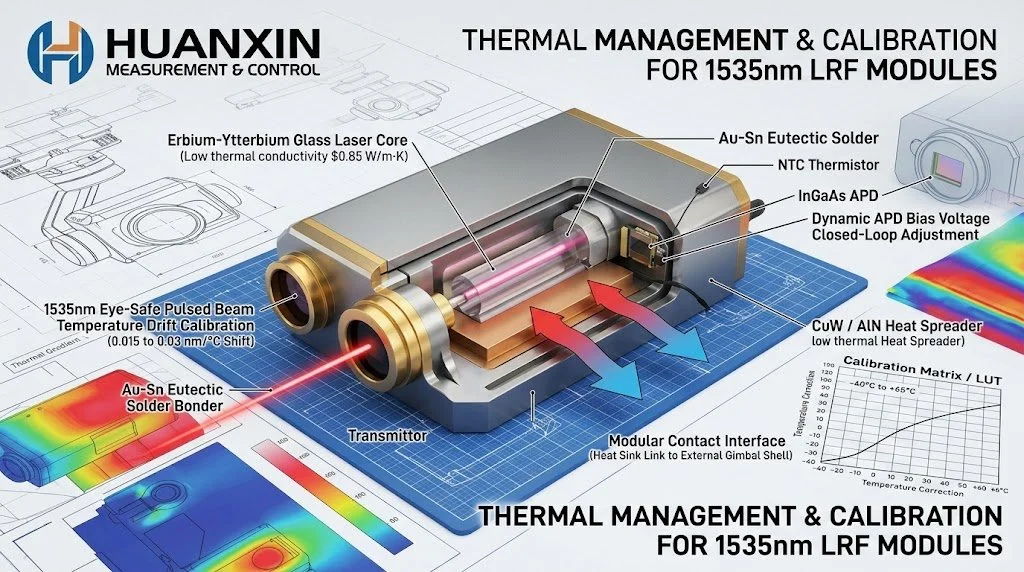
Modern high-performance modules embed a negative temperature coefficient (NTC) thermistor directly onto the APD submount. An onboard microcontroller samples this temperature and continuously updates the reverse bias voltage using a low-noise, digitally controlled high-voltage DC-DC converter. By tracking the APD's temperature-breakdown curve, the system keeps the multiplication gain steady from -40℃ to +65℃.

Heat Dissipation for Miniature LRF Drone Gimbals

Integrating a high-energy laser rangefinder into a stabilized electro-optical/infrared (EO/IR) drone gimbal poses strict space and weight constraints. Gimbals are sealed against moisture, dust, and pressure changes, which rules out active cooling fans and open-air convective cooling

Integrated Thermistor Monitors APD Substrate Temperature
Microcontroller Reads Temperature & Checks Calibration LUT
Low-Noise High-Voltage DC-DC Adjusts Bias (Vbias)
High Temperature / High Vbr

Increase Vbias to maintain constant avalanche multiplication gain.

Low Temperature / Low Vbr

Reduce Vbias to prevent excessive avalanche gain and unwanted noise triggers.

Key thermal packaging techniques for miniature gimbals include:

  • Eutectic Solder Die Attach: Using Gold-Tin (Au80Sn20) solder to attach pump diodes and laser crystals directly to Copper-Tungsten (CuW) or Aluminum Nitride (AlN) heat spreaders provides a thin, void-free metallic joint with high thermal conductivity (> 150 W/(m·K)), avoiding the thermal resistance of elastomeric gap pads.
  • Structural Heat Conduction Paths: The aluminum module housing serves as both an optical reference bench and the primary heat conductor. Mounting faces are precision-lapped to mate directly with the drone gimbal’s outer structural frame, allowing the gimbal's exterior skin to act as an effective radiative heat sink.

  • Thermally Isolated Optical Benches: Thermal isolation barriers separate the laser pump cavity from the receiver's APD and sensitive timing electronics. This isolates the detector from the heat generated during rapid laser bursts.

Factory Multi-Point Calibration for Wide-Temperature Applications

Advanced hardware design prevents catastrophic thermal failure, but software calibration ensures consistent sub-meter accuracy across wide operational ranges.

At Huanxin Measurement & Control Technology Co., Ltd., modules undergo automated environmental testing across the entire temperature profile before deployment.

Automated Environmental Chamber Testing
Temperature sweep from -40°C to +65°C in 5°C increments
Data Acquisition & Profiling
  • APD optimum bias vs. dark noise floor
  • Optical pulse output energy and baseline pulse shape
  • Discriminator propagation delay and zero-point offset
  • Master reference clock frequency stability
Generation of Non-Volatile Multi-Point LUTs
  • Dynamically adjusts APD bias across changing temperatures
  • Applies real-time corrections to flight-time measurements
  • Tunes pump pulse duration to manage thermal loading at high temperatures

During testing, automated targets gather performance metrics at regular temperature intervals. The system monitors:

  1. Optimal APD bias points relative to baseline dark noise.
  2. Receiver channel zero-point propagation delay variations.
  3. Master reference clock drift curves.
  4. Optical energy thresholds and pulse shapes.

These measurements populate non-volatile Look-Up Tables (LUTs) stored within the rangefinder's onboard flash memory. During field operation, an integrated MCU samples onboard sensors before each shot, referencing the calibration matrix to adjust APD bias, update the zero-point correction offset, and select the optimal trigger threshold.

Customized High-Precision 1535nm LRF Solutions

Standard off-the-shelf rangefinder modules often fall short when dealing with non-standard payload volumes, unusual heat sinking constraints, or specialized optical architectures.

Huanxin Measurement & Control Technology Co., Ltd. develops and manufactures high-performance pulsed 1535nm laser rangefinder modules tailored to demanding military, defense, and industrial applications. Our engineering capabilities include:

  • Custom optical layouts engineered for specific gimbal sizes and weight budgets.
  • Tailored structural and thermal interface profiles that match your payload's cooling surfaces.
  • Factory temperature calibration options extending from −40°C to +65°C (expandable to +85°C storage).
  • Specialized communication protocols, high-shock survivability modifications, and customized target discrimination algorithms.

For detailed technical specifications, application-specific designs, or custom module inquiries, visit laserrangefinder.cc .

Frequently Asked Questions

Why does Erbium phosphate glass build up heat faster than Nd:YAG during repetitive firing?

Phosphate glass has lower thermal conductivity (≈ 0.85 W/(m·K)) compared to crystalline hosts like Nd:YAG (≈ 14 W/(m·K)). The heat generated by optical pumping stays trapped within the core rather than conducting quickly to the outer casing, making it more prone to thermal lensing at higher repetition rates.

How does ambient heat degrade maximum target detection range?

High temperatures reduce pulse peak power, increase APD dark-current noise, and cause transmitter wavelength drift. If the laser's output shifts away from the receiver's narrow bandpass filter, return signals are attenuated, making distant targets hard to distinguish from background noise.

Can digital calibration offset all thermal drift issues in an LRF module?

No. Software lookup tables compensate well for electronic propagation delays, clock drift, and APD gain shifts. However, they cannot fix physical beam divergence caused by thermal lensing or direct optical power loss. Those issues must be handled through effective conductive mechanical heatsinking.

What is the advantage of Au-Sn eutectic soldering over silicone thermal pads?

Au-Sn (Gold-Tin) eutectic solder forms a continuous, rigid metallic bond with thermal conductivity exceeding 50 W/(m·K) and an ultra-thin bond line. Silicone thermal pads often range between 1–6 W/(m·K) and have higher contact resistance, which limits heat transfer in compact, sealed enclosures.

How does extreme cold affect a wide-temperature 1535nm rangefinder?

In sub-zero conditions, the APD breakdown voltage drops. If the bias voltage is not reduced accordingly, excessive avalanche gain and increased noise may occur, potentially affecting receiver stability. Cold temperatures also shift the pump diode's wavelength below the optimal absorption band of the laser glass, which reduces output pulse energy unless properly compensated.

Next
Next

Thermal Drift and Stability in 1535nm Laser Rangefinders: Operating from -40°C to +65°C