Mounting an optical payload onto an uncrewed aircraft, an armored vehicle, or a tripod in field conditions exposes it to severe environmental swings. A system might sit inside an uninsulated transport bay at -40°C overnight, then spend midday operating in direct sunlight where internal gimbal temperatures soar past +60°C.
For time-of-flight electro-optics, these temperature swings are brutal. Metal expands, glass changes its refractive index, semiconductor bandgaps shift, and laser cavity efficiencies drop. If an optical transceiver lacks proper thermal hardening, its beam drifts off target, pulse energy falls below the link budget, and measurement queries return empty errors.
Delivering reliable range measurement across a 105°C span requires understanding where performance breaks down and how mechanical and electronic compensation keep an optical line of sight intact.
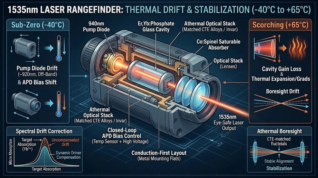
What Happens to Erbium-Glass Lasers Across Temperature Extremes
The 1535nm wavelength is ideal for tactical rangefinding because it falls squarely in the eye-safe infrared window. The human cornea and lens absorb this light, protecting the retina and allowing pulse energies high enough to punch through several kilometers of atmospheric haze without violating Class 1 eye-safety rules.
Thermal Impact on Core Rangefinder Subsystems
Thermal management is not limited to keeping the laser core firing. The receiver, structural housing, and internal electronics all face distinct thermal bottlenecks.
Combating Boresight Misalignment and Timing Errors
When engaging targets at 5km to 15km, angular tolerance is unforgiving. A deviation of just 0.4 milliradians means your emitted beam center lands 4 meters away from the receiver's field of view. The echo misses the collector lens entirely.
2. Closed-Loop APD Gain Control
Indium Gallium Arsenide Avalanche Photodiodes (InGaAs APDs) detect the faint return signal, which often arrives with only a few nanowatts of power. The diode's breakdown voltage drifts by roughly 0.1 to 0.2/℃.
Leaving that voltage fixed will blind the unit in hot conditions (due to lost multiplication gain) or push it into continuous, noisy avalanche breakdown in extreme cold. A built-in thermistor beside the APD feeds temperature data directly into a dedicated high-voltage supply, adjusting bias millivolt by millivolt to maintain a flat signal-to-noise ratio across the entire operating window.
Thermal Dissipation in Sealed Gimbals and Compact Payloads
Integrating a laser rangefinder into an aerial turret or an uncrewed ground vehicle payload introduces another constraint: no airflow.
These payloads are hermetically sealed against dust, sand, rain, and humidity. Convective cooling with internal fans is useless because heat has nowhere to go. At the same time, the laser module must share tight quarters with heat-generating video processors, motor drivers, and continuous-zoom lens actuators.
To prevent thermal build-up during burst-firing sequences:
Conduction-First Layout: The transceiver housing features precision-milled reference flats designed to mate directly with the host payload's aluminum or magnesium frame.
Low Thermal Resistance Interfaces: Phase-change thermal interface materials or compressible graphite pads bridge micro-gaps between the module base and the gimbal bulkhead, avoiding air pockets that act as insulators.
Separation of Electronics and Cavities: Power driver circuits that dump heat during rapid pulsing are kept physically separated from the temperature-sensitive erbium glass core.
OEM Capabilities from Huanxin Measurement & Control Technology
Selecting or customizing a rangefinder requires balancing weight, optical aperture, beam divergence, and power draw against your platform's volume constraints. Huanxin Measurement & Control Technology Co., Ltd. engineers and manufactures rugged, eye-safe laser rangefinder modules built specifically for wide-temperature defense and commercial systems.
Every module undergoes environmental screening—including dynamic thermal chamber testing from -40°C to +65°C, high-shock survivability profiles, and nitrogen-purged sealing to eliminate internal moisture condensation.
Our engineering team works directly with system integrators to configure:
Custom Optical Form Factors: Coaxial or dual-aperture configurations shaped to fit restricted gimbal front windows.
Electrical Interfaces: RS-422, RS-232, or UART TTL communication with tailored packet structures and status reporting.
Beam Shaping: Divergence optimization matched to target dimensions, maximizing signal return at extended ranges.
Harsh-Environment Sealing: Inert-gas-purged, hermetic enclosures designed for marine and high-altitude airborne operations.
Keeping Ranging Precision Intact
Operating reliably across a -40°C to +65°C range is not achieved with a single feature. It is the cumulative result of matching optical glass to alloy mounts, dynamically adjusting laser diode pump parameters, regulating APD bias voltages, and designing reliable thermal conduction paths into the host structure. When these elements work together, the system tracks targets consistently from cold morning starts to long missions in desert heat.
Frequently Asked Questions
Why does 1535nm light maintain better eye safety than 905nm or 1064nm emitters?
The human cornea and ocular lens absorb light in the 1535nm short-wave infrared band, preventing it from reaching and focusing on the retina. In contrast, 905nm and 1064nm wavelengths pass through the eye and focus down onto retinal tissue, multiplying energy density thousands of times and risking permanent blind spots. This ocular absorption allows 1535nm systems to emit higher energy pulses under Class 1 eye-safe conditions.
How does thermal drift cause range readings to shift by several meters?
When temperature climbs, receiver optical filters shift, changing how light enters the system. Rising heat also alters comparator thresholds and internal propagation delays within detection circuits. If the threshold comparator triggers late on a pulse with a degraded rise time, the calculated time-of-flight lengthens, shifting the measured distance. Using dynamic thresholding and temperature-compensated crystal clocks keeps that drift to within ±1 meter.
Can an unheated 1535nm module start instantly at -40°C?
Yes, provided the driver circuitry dynamically compensates for the pump diode's spectral shift. Modern wide-temperature modules adjust pump drive currents and duration to compensate for the lower absorption efficiency of the gain medium, delivering nominal pulse energy within the first few pulses without waiting for slow pre-heating routines.
What is the practical difference between coaxial and dual-aperture rangefinder optics?
Coaxial optics send the outgoing pulse and receive the incoming echo through a shared primary aperture, reducing front-window footprint and eliminating parallax issues at short ranges. Dual-aperture designs use separate lenses for transmission and reception. While dual-aperture setups require slightly more window space, they provide superior optical isolation, preventing transmitter backscatter from blinding sensitive APD receivers.
How does Huanxin handle custom mechanical integration for unusual gimbal geometry?
Huanxin works directly from client-supplied CAD models and volume constraints. The engineering team can alter housing profiles, adjust optical centerline heights, relocate connector headers, and provide custom conductive mounting surfaces to ensure the module fits within the target payload without sacrificing thermal dissipation paths.