Imagine pointing an electro-optical payload at a structure just a few meters ahead, only for your display to output zero. In tactical tracking and field robotics, a sensor that goes dark up close is as compromised as one that cannot see far. At the same time, keeping lock on fast-moving targets demands sustained, high-speed pulse trains without overheating the enclosure.
In pulsed Time-of-Flight (ToF) optics, optimizing the laser rangefinder minimum range while maximizing the laser repetition rate requires a fine balance between optoelectronic recovery, thermal transfer, and optical isolation.
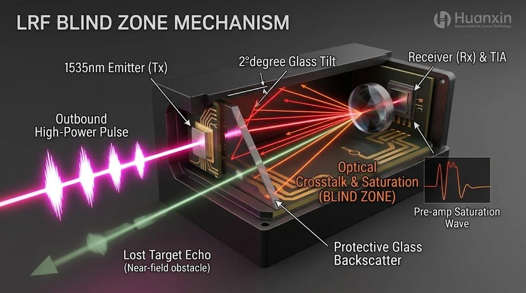
What Causes the LRF Blind Zone?
A pulsed laser system calculates target distance by timing the journey of brief photon packets travelling at roughly 30 cm per nanosecond:
If an optical pulse lasts 5 ns, that burst spans approximately 1.5 meters along its path of travel.
To register returns from objects kilometers downrange, an InGaAs Avalanche Photodiode (APD) operates under high reverse bias, primed to catch micro-watt returns. When the transmitter fires, high-energy stray light inevitably enters the receiver cavity through chassis seams or protective cover glass reflections.
This high-intensity scatter saturates the APD and overloads the transimpedance amplifier (TIA), creating an operational dead zone known as the LRF blind zone. Until trapped carriers clear out and amplifier voltage returns to baseline, any echo arriving from a nearby target is lost in the saturation noise floor.
How to Reduce Blind Zone in Pulsed LRF Systems
Shortening the close-in boundary requires physical isolation and rapid electronic recovery working together.
1. Structural and Optical Isolation
Independent Optical Windows: Housing transmitter and receiver optics behind isolated apertures stops internal reflection at the source.
Tilted Protective Glass: Canting the shared outer protective window by 2° to 5° directs specular surface bounce away from the receiver aperture.
Internal Baffling: Integrating knife-edge aperture rings and absorbing carbon finishes within the barrel captures wide-angle scatter before it strikes the detector face.
2. High-Speed Analog Signal Conditioning
Fast Schottky Clamping: Placing sub-nanosecond Schottky diodes across the TIA input clips overdrive voltages, letting the front end recover in nanoseconds rather than microseconds.
Dynamic Time-Gated Gain: Lowering APD bias voltage below breakdown during the initial firing phase suppresses current surges from local scatter. Raising bias back to operational levels 15–30 ns later brings the receiver to full sensitivity just in time for short-range echoes.
Differentiating Discriminators: Passing incoming pulses through high-order differentiators highlights sharp zero-crossing points, making it possible to pull real returns out from the declining tail of the main pulse.
Mastering Laser Repetition Rate in Dynamic Targeting
Stationary targets tolerate slow measurements, but operational environments rarely stay still. Moving to higher pulse frequencies transforms basic range detection into dynamic situational awareness.
High Frequency Ranging for Moving Targets
When monitoring a small drone flying at 30 m/s, a 1 Hz pulse provides one position update every thirty meters. In contrast, 10 Hz to 20 Hz repetition rates deliver updates every few meters, keeping Kalman filters stable and line-of-sight locks reliable even through brief physical interruptions.
1535nm Repetition Rate vs Thermal Dissipation
While operating frequencies in the multi-hertz range improve tracking accuracy, they introduce serious thermal hurdles, particularly within compact 1535nm eye-safe architectures.
Erbium-ytterbium co-doped phosphate glass lasers emit at 1535nm—an eye-safe band that offers strong atmospheric penetration and minimal optical noise. However, phosphate glass has a low thermal conductivity of roughly 0.85 W/m·K.
Running continuously at elevated frequencies concentrates heat in the core of the rod:
Thermal Lensing: Internal temperature gradients bend light unevenly, broadening beam divergence and reducing energy density at the target.
Gain Saturation: Elevated glass temperatures trigger thermal populating of lower laser states, degrading output energy per pulse.
Cavity Quenching: Without effective heat transfer, the gain medium can stop lasing entirely during extended operations.
Practical Heat Management in Compact Gimbals
Small electro-optical gimbals often lack the space or power budgets for cooling fans. Stabilizing higher repetition rates in tight spaces relies on:
Direct Metallic Clamping: Mounting laser gain rods inside copper-tungsten (CuW) or aluminum nitride (AlN) sleeves channels heat directly toward payload chassis walls.
Burst-Mode Firing Profiles: Operating at 10 Hz to 20 Hz during initial target acquisition, then dropping to a cooler 1 Hz to 2 Hz cadence for steady tracking, keeps internal heat within workable bounds.
Trade-Off Matrix: Short-Range Detection vs. High Repetition Rate
OEM Integration with Huanxin Optoelectronics
Balancing close-range response with thermal endurance requires cohesive mechanical, optical, and board-level design.
Huanxin Measurement & Control Technology Co., Ltd. develops and manufactures specialized 1535nm pulsed laser rangefinder modules for defense, maritime, drone, and industrial integrations. Operating from cleanroom production spaces in Changchun, China, Huanxin delivers modules covering operational distances from 3 km to 20 km:
Ultra-Lightweight Footprints: Compact architectures starting under 29 grams integrate easily into weight-restricted UAV pods.
Reduced Blind Zones: Specialized analog receiver circuits shorten minimum detection ranges down to a few meters.
Versatile Digital Control: Standard TTL and RS-422 serial interfaces support adjustable pulse firing, status polling, and multi-target logging.
Custom OEM Engineering: Comprehensive customization covers optical barrel configurations, interface pinouts, custom chassis shapes, and tailored heat-sinking profiles.
Frequently Asked Questions
What main factors define the minimum measurement range of a pulsed LRF?
The minimum range depends on three main variables: the optical pulse width, internal optical reflection between emitter and receiver channels, and how quickly the photodiode preamplifier recovers from initial saturation.
Why is 1535nm preferred for tactical ranging platforms?
The 1535nm band is eye-safe because light at this wavelength is absorbed by the cornea and lens before reaching the retina. This permits higher peak pulse powers without eye safety risks, while maintaining low scattering across atmospheric moisture, smoke, and haze.
Does a higher pulse repetition rate reduce effective detection range?
If the laser's thermal footprint is properly managed, individual pulse energies remain constant, keeping maximum range intact. However, if heat builds up inside an uncooled cavity, thermal lensing degrades beam quality and drops output energy, which pulls in the maximum measurement limit.
How does multi-echo signal processing handle near-field obstacles?
Multi-echo processing uses high-speed digitizers to log multiple signal peaks from a single outgoing pulse. If foreground clutter—such as tree branches or window glass—reflects part of the beam, the processor logs that close reflection while continuing to register the primary target further downrange.
Can standard LRF modules be customized for non-standard gimbal spaces?
Yes. Huanxin provides OEM customization across optoelectronic designs, including custom circuit board layouts, modified optical positions, tailored chassis geometry, and firmware-level communication adaptations.