Laser rangefinders deployed in field environments rarely operate under lab conditions. An electro-optical payload scanning a valley must contend with tree canopies, rain, ocean spray, dust kicked up by tracked vehicles, and deliberate concealment screens. A standard single-return unit often fails in these conditions, measuring the distance to an overhead twig or a fog patch rather than the vehicle sitting two kilometers downrange.
Deploying a multi-echo laser rangefinder solves this breakdown. By segmenting incoming reflections along the beam path into separate arrival bins, modern optical modules let mission computers filter out foreground clutter and track genuine targets.
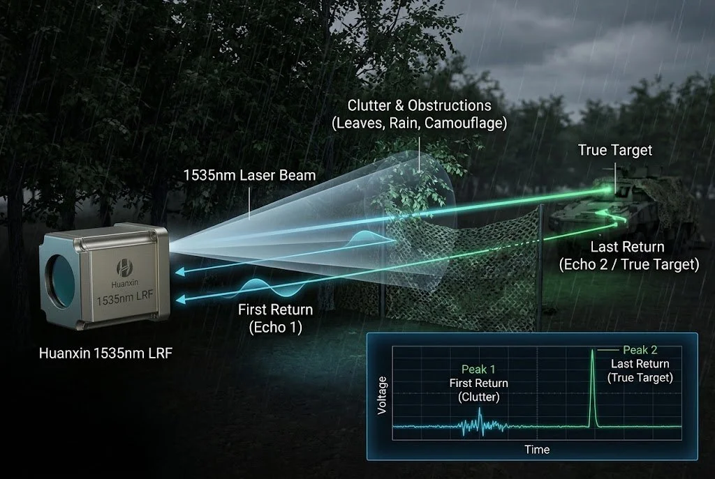
The Optical Ranging Dilemma in Degraded Sightlines
At its core, pulsed laser ranging measures the round-trip flight time of an optical burst. When that burst travels through clean air to a flat wall, you get a clean return. Out in the field, things get messier.
Because laser beams diverge as they travel, a 0.5 mrad beam spreads to a 50 cm footprint at 1 km and 5 m at 10 km. Any physical object entering this widening cone reflects a portion of the photons back to the sensor.
In rough conditions, the receiver gets hit by a train of pulses rather than a single peak:
Airborne Particles: Fog, sea spray, and rain cause Mie scattering, bouncing photons back almost immediately.
Foliage & Tree Cover: Branches, pine needles, and leaves reflect the outer edges of the beam footprint while letting the center pass through.
Concealment Nets: Synthetic netting disrupts vehicle silhouettes, bouncing part of the signal while allowing leaked photons through the gaps.
How Multi-Target Discrimination Works in Pulsed Laser Rangefinders
To turn a chaotic return into usable telemetry, the sensor processes the entire incoming signal over time instead of tripping on the first pulse that crosses a static voltage threshold.
The receiver uses an InGaAs Avalanche Photodiode (APD) paired with high-gain transimpedance amplification. When light bounces off multiple obstacles, the APD produces multiple voltage spikes.
High-speed timing counters and digital sampling convert these spikes into separate distance readings. The processor then runs pulse-shape checks to verify the signal: diffuse returns from fog clouds are discarded, while sharp, high-amplitude spikes from solid structures are cataloged for targeting.
Why 1535nm Erbium-Glass Outperforms 905nm and 1064nm
Module designers must balance wavelength physics against operational safety:
Water in the human eye absorbs 1535nm light in the cornea before it reaches the retina. This allows high peak power output without risking ocular damage, delivering the link margin needed to punch through adverse atmospheric conditions.
Difference Between First Pulse and Last Pulse Laser Rangefinder
How a module reports data depends entirely on its gate logic. Most multi-target units let the host computer switch modes dynamically.
First Pulse Logic
Prioritizes the closest physical object. A reconnaissance drone hugging a ridgeline at 60 knots uses this mode to avoid nearly invisible power lines or bare tree branches before they clip a rotor.
Last Pulse Logic
Deliberately bypasses foreground noise. By ignoring early returns from brush or dirty optical windows, the system isolates the solid target at the far end of the optical path.
Measuring Target Distance Through Camouflage Netting with 1535nm LRF
Defeating modern camouflage nets comes down to optical link budget and geometric porosity. Camouflage screens are never solid walls; they rely on perforated vinyl leaves and breathable mesh to vent wind and stay lightweight.
Energy Division: As the 1535nm beam footprint expands across the net, roughly 60% to 80% of the photons hit the synthetic mesh. The remaining 20% to 40% pass straight through the gaps.
Reflection & Return: The photons striking the metal or composite hull behind the net reflect back through those same mesh openings toward the rangefinder aperture.
Pulse Discrimination: The APD records two distinct returns separated by a few nanoseconds.
Target Extraction: Applying clutter rejection laser ranging algorithms, the signal processor evaluates return signatures. The net returns a diffuse, scattered pulse, while the vehicle hull produces a crisp, high-density return. The module discards the first echo and locks its fire-control solution onto the vehicle.
Reducing False Returns from Rain Dust and Smoke in OEM Rangefinders
Operating in maritime fog, sandstorms, or battlefield smoke requires hardware-level protections alongside digital filtering:
Time-Programmed Gain (TPG): Near-field dust particles bounce photons directly into the aperture with massive relative amplitude. TPG keeps receiver sensitivity suppressed for the first few fractions of a microsecond, ramping up gain as range increases. This prevents nearby particles from saturating the detector.
Pulse Width Validation: Liquid droplets and aerosols stretch a 5 ns laser pulse into a 15–30 ns return. Hardware discriminators measure pulse rise times, rejecting smeared waveforms while passing sharp, unmodified reflections.
Optical Window Tilt: Mounting protective housing windows with a 1° to 3° mechanical tilt prevents direct specular back-reflection from the module's own emitter into its receiver channel.
OEM Integration: Huanxin Laser Rangefinder Solutions
Fitting a high-performance multi-echo system into strict size, weight, and power (SWaP) budgets is a core design hurdle for optical payload builders. Off-the-shelf units rarely align with bespoke gimbal bays or unique communication protocols.
Huanxin Measurement & Control Technology Co., Ltd. develops and manufactures 1535nm eye-safe laser rangefinder modules for direct OEM integration across defense, industrial inspection, and airborne surveillance systems:
Engineering Customization Services
Dynamic Protocol Support: Configurable TTL and RS-422 serial interfaces for drop-in sync with flight controllers and ballistic computers.
Athermal Optical Design: Mechanically stabilized cavities and temperature-drift compensation ensure zero boresight shift across -40°C to +65°C.
Tailored Multi-Echo Firmware: Custom-tuned firmware to prioritize first, last, or strongest echo trains based on specific operating requirements.
Mechanical Adaptation: Custom form factors, bespoke bracket layouts, and matched SWIR anti-reflective window assemblies.
Frequently Asked Questions
Can a 1535nm multi-echo rangefinder penetrate solid walls?
No. Optical lasers cannot pass through opaque, solid surfaces like brick, steel, or stone. Multi-echo systems rely on physical gaps in porous obstructions—such as foliage, camouflage netting, fences, or airborne particulate screens—to capture photons that reach the target behind them.
What is the minimum target separation distance a multi-echo module can resolve?
Target separation depends on pulse duration and detector response speed. A module using a 5 ns pulse width can distinguish targets spaced roughly 1 to 1.5 meters apart along the same optical line of sight. Objects closer than this blend into a single stretched return.
How does continuous repetition rate affect heat and power draw?
Single-shot ranging pulls minimal standby current. Running a 1535nm module continuously at 1 Hz to 10 Hz for moving-target tracking generates significant thermal load on the internal pump diode and driver electronics. Systems using continuous tracking require careful heat sinking and regulated input power to prevent wavelength drift and link loss.
Can the rangefinder output every detected echo to the host system?
Yes. Depending on firmware configuration, Huanxin modules can output the full target table (first, second, and third return distances with relative signal strengths) over RS-422 or TTL, giving host mission computers complete control over signal processing.
Why choose 1535nm over 905nm for drone-mounted gimbals?
A 905nm module drops range rapidly in haze, struggles past 1.5–2 km, and risks eye damage at the power levels needed for long-range work. The 1535nm wavelength remains eye-safe at significantly higher pulse energies, pierces atmospheric dust and smoke, and scales easily to 5–20 km detection envelopes in lightweight, sub-100-gram packages.